B. Make sure the phase hole of the Main Cam Gear on the bottom side
of Mechanism Unit is in EJECT position.
Fig. D3
C. Install the Mechanism Chassis straight onto the Main C.B.A. so that
the Sensor LED clears the hole in the Mechanism Chassis and that 3
Connectors (P3501, P4001, P6201) are aligned and seated securely.
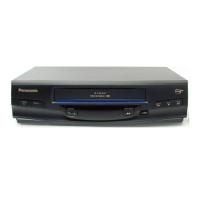
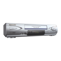
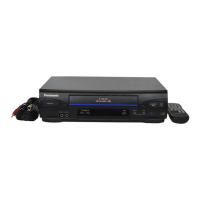
5.2. MECHANISM SECTION
Refer to the Service Manual for R4-Mechanism Chassis for PV-Model (Order No. MKE0401000C1).
6. SCHEMATIC DIAGRAMS
6.1. SCHEMATIC DIAGRAM & CIRCUIT BOARD LAYOUT NOTES
6.2. MAIN SCHEMATIC DIAGRAMS
6.3. INTERCONNECTION SCHEMATIC DIAGRAM
6.4. VOLTAGE CHART
16

 Loading...