22
Inter-unit
power wiring
Power wiringInter-unit
control wiring
8P terminal board
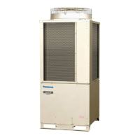
C Type (Outdoor Unit)
U1 U2 1 2 G L1 L2
Indoor Unit
Type
Time delay fuse or
circuit capacity
U1, K1, T1, F1 15 A
Control Wiring
(A) Inter-Unit Control Wiring (B) Remote Control Wiring (C) Control Wiring For Group Control
AWG #18
Use high voltage wire (300 V)
*
1
AWG #18
*
2
(0.75 mm
2
) AWG #18
*
2
- (0.75 mm
2
)
Max. 3,300 ft. Max. 1,650 ft. Max. 650 - ft. (Total)
AWG=American Wire Gauge
*
1
With ring-type wire terminal
*
2
Wire joint connection
4-3. Wiring System Diagrams
Basic wiring diagram for standard control
NOTE
Disconnect switch may be needed by the National/Local code.
ALWAYS COMPLY WITH NATIONAL AND LOCAL
CODE REQUIREMENTS.
NOTE
(1) Refer to Section 4-2. Recommended Wire Length
and Wire Diameter for Power Supply System for the
explanation of “A”, “B” and “C” in the above diagrams.
(2) Inter-Unit Control Wiring (A) and remote control wiring
(B), (C) have no polarity. But for other wiring, respect
polarity. Be sure to connect as shown in the Wiring
System Diagram.
(3) In case of separate supply connection to indoor unit,
over current protection must be provided between
power source and indoor unit.
MAXIMUM OVER CURRENT PROTECTION 15 A
(FUSE OR HACR TYPE CIRCUIT BREAKER)

 Loading...