EasyManua.ls Logo

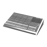
Panasonic RAMSA WR-S208 - Mono Input Section Control Descriptions

Panasonic RAMSA WR-S208
28 pages
To Next Page IconTo Next Page
To Previous Page IconTo Previous Page
Loading...
MONO INPUT SECTION
(1)
Input
Selector
Switches
IMicJLine)
These
selector
switches
are used
for
selecting
either
the
microphone
Input
or line i
nput
,
Both
microphone
input
and
line
input
are elec-
tronically
bala
need
,
If
both
the
Mic
and
Line
switches
are
si
multa
neously
pressed
,
line
Input
is
selected.
12)
Mic/Line
Trim
Control
A
control
to
adjust
the
input
level
of
a
microphone
or
line
input
over
a
range
of
40
dB :
Trim
at
0
-rim
at
-40
Mic
60
dB
-20
dB
Line
-30
dB
-I-
10
dB
(3)
Peak
level
Indicator
LED
When
the level
of
an Inpt,;t signal reaches a value
6 dB
lower
than
the
maxim
um
output
lev
el,
the
peak
Ind i
cator
LED
w ill lig
ht.
The
peak
level
IS
'Ionitored
at
two
POints,
at
the
preamplifier
and
after
the
equal
izer.
When
this
;"'ED
lights,
the
input
signal
w ill be
cfstorted,
(4)
Equalizer
Three
-
band
equalizer
:
The
high
and
low
bands
are a
shelving
type
with
turnover
frequencies
of
i 0
kHz
and
100
Hz
respect
iv
ely.
The
mid band
is
a peaking
type
with
a variable freq uency range
of
400
Hz -
6.3
kHz.
High
:
±·5dB(
±
12dBatl0kHz)
Shelving
type
1 -C )
Mid
'
±15
dB (400 Hz
to
6.3
kHz)
Peaking
type
(
-{}
)
Low:
±15
dB
(±12
dB
at
100
'-1z)
Shelving
type
( > )
(5)
Monitor
Control
This
control
is
used
to
adjust
th
e
le
vel se
n'
, to
the
mOI
'
it
or
bus
line. N.
cn
it
or
signals are
post
-
equalizer
/
pre-f
ader
.
Used
for
foldback
moni
~
Jring
,
(6)
Send
Control
ThiS
control
is
used
to
adJu
s.
the
level
to
the
Send
output.
(7)
Send
Selector
S>_
Jitch
(Pre/Post)
ThiS
switch
selects ei
ther
pre-fader
or
p(;
~;
t-fader
signals
for
the
Send
output
. Be
cause
Send
out-
put
can
be
sent
at
either
pre-fader
or
post
fader
level,
it
ca"1
be
used
as a
monitor
output
or
ef
-
fect
output
in a
variety
of
applications.
Pre: U
se
d
for
fold
back
monito
;·i:lg.
P
ost
:
Used
fo~
eci~:)
and
other
effects.
,
- 5 -
(81
Effect
Control
This is
the
level
control
to the
effect
output
,
Out-
put
signals
are
post-fader
signals
(9)
Pan
Control
This
knob
is
used
to
d
ivid
e
~'le
I
npLt
signal
bet-
ween
stereo
outputs
Sub
A and
Sub
B,
('
0)
Channel
Solo
S\
·
"tch
A
switch
for
monitoring
indiVidual
Input
chan-
nels
through
the
headphones,
Pressing the solo
switch
on the WR-S 21 ? or
WR-S216
causes
the
control
room
man
ITOr
slgn[':1
to
be repl aced
by
the
solo
si(;nE.l .
(11)
Channel
Fader
A
60
mm
c
arbon
fader
to
control
output
level
of
in
put
channels
, Fader
shou
ld
be
at " 0"
fo
r
the
rat
Dd
output
level.

Related product manuals