EasyManua.ls Logo

Panasonic RF-544 - User Manual

Panasonic RF-544
7 pages
Print Icon
To Next Page IconTo Next Page
Loading...
ORDER
NO.
MD9207070C2
Service
Manual
FM-AM
Portable
Radio
Radio
RF-544
Pa
aoe
Black
Type
Area
©
0
F.R.Germany
&
Italy
(EG)
i
SPECIFICATIONS
General
:
Radio
Section
:
Power
Requirement
:
AC;
230~240V,
50Hz
Frequency
Range
:
FM;
87.5
~
108
MHz
Battery;
6V,
four
R6/LR6
(UM-3)
batteries
AM;
520
~
1610
kHz
Power
Output
:
680mW
...RMS
(max.)
Intermediate
Frequency
:
FM;
10.7
MHz
Power
Consumption
:
3W
(AC
only)
AM;
459
kHz
Speaker
:
8cm
PM
Dynamic
Speaker
(4Q)
Sensitivity
:
FM;
18
dB/S50
mW
output
Jacks
:
Output;
Earphone
(8Q,
370mW)
(-3
dB
Limit
Sens.
)
Dimensions
:
222
(W)
x
121
(H)
x
79
(D)
mm
AM;
57
dB/m/50
mW
output
Weight
:
560g
without
batteries.
Notes
:
1.
Weights
and
dimensions
shown
are
approximate.
2.
Design
and
specifications
are
subject
to
change
without
notice.
Panasonic
Question and Answer IconNeed help?

Do you have a question about the Panasonic RF-544 and is the answer not in the manual?

Overview

This document is a service manual for the Panasonic RF-544, an FM-AM portable radio. It provides comprehensive information for maintenance, repair, and understanding the device's operation.

Function Description

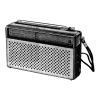
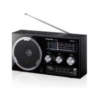
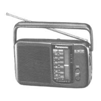
The Panasonic RF-544 is a portable radio designed for receiving both FM and AM broadcasts. Its primary function is to provide audio entertainment through radio reception, offering a choice between frequency modulation (FM) and amplitude modulation (AM) bands. The device is designed for portability, indicated by its "portable radio" designation and the option to operate on batteries, making it suitable for use in various locations without requiring a constant power outlet.

Important Technical Specifications

General:

  • Power Requirement: The radio can operate on AC 220-240V, 50Hz, or on batteries. It requires four R6/LR6 (UM-3) batteries, providing 6V (max).
  • Power Output: The maximum power output is 600mW (RMS) at 10% total harmonic distortion (THD) when operating on AC.
  • Speaker: It features an 8Ω, 7.7 cm (3") permanent dynamic speaker, capable of handling 800mW.
  • Dimensions: The radio measures 252 (W) x 121 (H) x 79 (D) mm.
  • Weight: It weighs 560g without batteries.

Radio Section:

  • Frequency Range:
    • FM: 87.5 - 108 MHz
    • AM: 520 - 1610 kHz
  • Intermediate Frequency:
    • FM: 10.7 MHz
    • AM: 450 kHz
  • Sensitivity:
    • FM: 18 dB/50 mW output
    • AM: 57 dB/50 mW output

Model Suffixes and Corresponding Areas: The manual specifies different suffixes for the model number, indicating the intended geographical market:

  • (E): Europe
  • (EB): Great Britain
  • (EG): F.R. Germany & Italy

Usage Features

The RF-544 is designed for straightforward operation. Users can select between FM and AM bands to tune into their desired radio stations. The portable nature, supported by battery operation, allows for flexible use in various environments. The physical layout of the device, as shown in the cabinet parts location diagram, suggests standard controls such as a tuning knob, band selector, and volume control. The presence of a headphone jack (JK101) allows for private listening. The internal speaker provides audio output for general listening. The AC power cord (A4) is detachable, further enhancing portability and ease of storage.

Maintenance Features

The service manual provides detailed information crucial for maintaining and repairing the RF-544.

Schematic Diagram: A comprehensive schematic diagram (CXA1019S) illustrates the internal circuitry, including the main circuit and power supply circuit. This diagram is essential for troubleshooting and understanding the electrical connections and component functions. Key components like the AF power amplifier, discriminator, and various ICs (e.g., IC1) are clearly labeled.

Measurements and Adjustments: This section outlines the procedures for aligning the radio's performance.

  • AM-IF Alignment: Instructions are provided for adjusting the AM intermediate frequency (IF) to ensure optimal reception. This involves connecting a signal generator and an oscilloscope/voltmeter to specific test points (T1, T3, CT1-1, CT1-2, CT1-3, CT1-4) and adjusting coils (L3) and trimmers.
  • AM-RF Alignment: This procedure focuses on aligning the AM radio frequency (RF) section, including adjusting the oscillator and antenna coils (L3) and trimmers (CT1-1, CT1-2, CT1-3, CT1-4) for maximum output at specific frequencies (459kHz, 1650kHz, 550kHz, 1500kHz).
  • FM-IF Alignment: Details are given for aligning the FM IF section, using a signal generator and voltmeter/oscilloscope connected to test points (TP1, TP2, TP3, TP4) and adjusting the FM IF coil (L5) and trimmer (CT1-1, CT1-2).
  • FM-RF Alignment: This involves aligning the FM RF section, adjusting the FM oscillator (L5) and antenna (L3) coils and trimmers (CT1-1, CT1-2) at frequencies like 88.2MHz, 100.2MHz, and 106MHz.
  • Alignment Instructions: General instructions include setting volume control to maximum, setting band switch to AM or FM, and using a signal generator with a 400Hz modulation.

Terminal Guide of IC's, Transistors & Diodes: This section provides pinout diagrams and identification for integrated circuits (IC1: CXA1019S) and diodes (RVD1SR1139TA), which is vital for component replacement and circuit analysis.

Cabinet Parts Location: An exploded view diagram illustrates the physical arrangement of all cabinet parts, making it easy to identify and locate components during disassembly and reassembly. Key parts like the power transformer (T101), speaker (12), and various switches (S1) are labeled.

Replacement Parts List: A comprehensive list of replacement parts is provided, categorized into:

  • Cabinet & Chassis: Includes parts like front cabinet, rear cabinet, dial panel, knobs, and handles.
  • Variable Capacitors: Lists variable capacitors and trimmers.
  • Coils & Transformers: Details various coils (e.g., FM OSC, AM OSC, FM IF, AM IF) and the power transformer.
  • Filter(s): Specifies ceramic filters (CF1, CF2).
  • Fuse(s): Lists the fuse (F1).
  • Switch(es): Includes the function switch (S1).
  • Integrated Circuit(s): Lists the main IC (IC1: CXA1019S).
  • Diode(s): Lists various diodes (D101-D104).
  • Jack(s): Specifies the headphone jack (JK101) and AC IN jack (JK1).
  • Accessories: Includes instruction manual and AC cord.
  • Variable Resistor(s): Lists variable resistors (VR1).
  • Packing Material(s): Lists gift box, polyfoam, and polybag.

Resistors & Capacitors: Detailed lists of resistors and capacitors are provided with their values, tolerances, and voltage ratings. This information is crucial for replacing faulty components with correct specifications. Notes clarify the meaning of symbols and markings for these components.

Overall, the manual is a complete guide for anyone involved in the service or repair of the Panasonic RF-544 portable radio, ensuring that the device can be maintained to its optimal operating condition.

Panasonic RF-544 Specifications

General IconGeneral
BrandPanasonic
ModelRF-544
CategoryPortable Radio
LanguageEnglish

Related product manuals