Do you have a question about the Panasonic RF-1150LB and is the answer not in the manual?
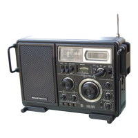
Lists the frequency bands covered by the radio, including FM, LW, MW, SW1, and SW2.
Specifies the IF frequencies for FM and AM reception, essential for tuning.
Details the signal strength required for a specific audio output level.
Indicates the maximum audio output power of the radio unit.
Outlines the power requirements, including AC voltage and battery types.
States the electrical power draw of the device during operation.
Describes the type and size of the built-in speaker.
Provides the physical measurements (width, height, depth) of the radio.
Lists the weight of the radio, excluding batteries.
Specifies the impedance ratings for the speaker and other connections.
Step-by-step instructions for safely removing the outer casing of the radio.
Guide on disassembling the mechanism that moves the dial pointer.
Detailed steps for correctly fitting the dial scale and cord onto the mechanism.
Instructions for routing and securing the dial cord for proper operation.
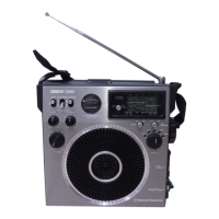
Steps for detaching the integrated rotating antenna from the unit.
Instructions for removing the protective housing for the gyro antenna.
Important preliminary steps and settings before performing radio alignment.
Detailed steps for aligning different frequency bands (LW, MW, SW1, SW2, FM-IF, FM-RF).
The complete circuit diagram showing all components and their interconnections.
Visual guide to component placement and wiring on the circuit boards.
Steps to align the Beat Frequency Oscillator for potential SSB reception.
Procedure for calibrating the battery and tuning indicator meters.
Illustrations showing the placement of external and internal cabinet components.
Diagrams indicating the positions of components on the main chassis.
List of semiconductor components with part numbers and descriptions.
List of miscellaneous components including operation compensators.
Part numbers for RF filters, inductors, and transformers.
Continued listing of coils and transformers with part details.
List of potentiometers and variable resistors used in the radio.
Details of tuning capacitors and trimmers.
Listings for combined components like coils with capacitors.
Specifics for the main speaker unit.
Part numbers for various function and control switches.
Comprehensive list of resistors with values, power, and tolerance.
Extensive list of ceramic, styrol, polyester, and electrolytic capacitors.
Part numbers for cabinet components and assemblies.
Part numbers for chassis-mounted components and hardware.
List of included accessories like earphones and power cords.
Details of packaging components used for shipping the product.
| Type | Portable Radio |
|---|---|
| Tuning | Analog |
| Output Power | 1.5 W |
| Wave bands | AM |
| Power Source | AC mains or battery |
| Antenna | Telescopic |