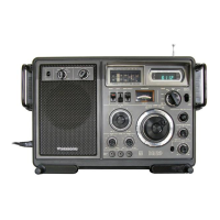
Do you have a question about the Panasonic RF-2900LBS and is the answer not in the manual?
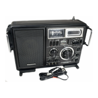
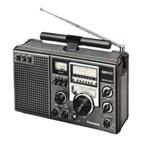
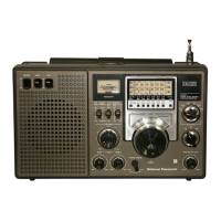
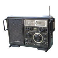
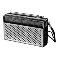
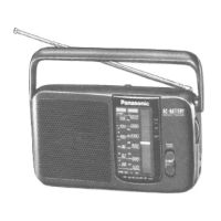
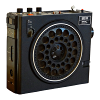
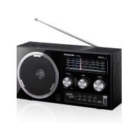
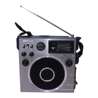
Identifies and lists all external controls, buttons, and indicators on the radio unit.
Details the step-by-step process for disassembling the radio, listing parts to remove.
Essential preparatory steps and general guidelines to follow before performing any alignment.
Detailed procedures for aligning AM, LW, and SW frequency bands for optimal performance.
Procedures for aligning the FM band, including IF and RF stages.
Steps for aligning the SW intermediate frequency and second oscillator circuits.
Steps to align SW RF stages (SW1, SW2, SW3) for maximum output.
Procedure for setting the tuning and battery indicator meter according to specifications.
Procedure for adjusting the Delayed Automatic Gain Control circuit for stable reception.
List of integrated circuits, transistors, diodes, thermistors, coils, transformers, and capacitors.
Lists cabinet parts, accessories, packing materials, and printed matter for the radio.
Details changes to the replacement parts list from the original service manual.
| Type | Portable Radio |
|---|---|
| Tuning Bands | FM, MW, LW, SW |
| FM Frequency Range | 87.5 - 108 MHz |
| LW Frequency Range | 150 - 285 kHz |
| Power Source | AC Power, Battery |
| Antenna | Telescopic Antenna |