This document provides comprehensive information about the Panasonic RF-D1 DAB Digital Radio, covering its functions, technical specifications, usage, and maintenance procedures.
Function Description
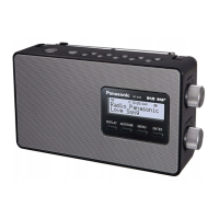
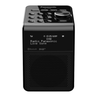
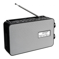
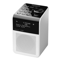
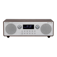
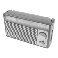
The Panasonic RF-D1 is a portable DAB (Digital Audio Broadcasting) digital radio, also capable of receiving FM radio broadcasts. It features a telescopic antenna for improved reception. The device is designed for ease of use with clearly labeled controls for volume, tuning, and various radio functions.
Key functional components include:
- Standby/on switch [U/I]: To power the unit on or off.
- Numbered buttons [+5, 1-5]: For direct selection of preset stations or other numbered functions.
- FM or DAB select button [TUNER/BAND]: To switch between FM and DAB radio modes.
- Tuning control: A rotary knob for FM frequency selection, DAB station tuning, menu navigation, and time adjustment.
- Volume control: A rotary knob to adjust the audio output level.
- Sound EQ/Sound virtualizer button [SOUND EQ/–S. VIRTUALIZER]: To activate sound equalization or a sound virtualizer feature.
- DAB primary/secondary select button [PRIMARY/SECONDARY]: For selecting primary or secondary DAB services.
- Display button [DISPLAY]: To cycle through different display information.
- Menu button [MENU]: To access the radio's menu options.
- Menu confirmation button [ENTER/–TIMER CHECK]: To confirm selections within the menu or check timer settings.
- Speaker: The unit includes two integrated speakers for audio output. It's important to note that the speakers do not have magnetic shielding, so the unit should not be placed near televisions, personal computers, or other devices easily influenced by magnetism.
- Headphone Jack (JK101): For private listening.
- Line Out (JK401): For connecting to external audio systems.
- DC IN (JK301): For connecting the AC adaptor.
The radio supports both AC power via an adaptor and battery operation (UM-2 x 6, 9V).
Important Technical Specifications
While specific numerical values for all technical specifications are not explicitly listed in the provided text, the document implies several important characteristics:
- Radio Frequencies: Supports both DAB (Digital Audio Broadcasting) and FM radio.
- Power Source: Operates on either AC power (via supplied adaptor) or 6 x UM-2 (size C) batteries (9V total).
- Speaker Impedance: The speakers are rated at 6 Ω (Lch and Rch).
- Battery Current Consumption (approximate values):
- Volume minimum output (FM): 145 mA
- Volume maximum output (FM): 255 mA
- Volume minimum output (DAB): 350 mA
- Volume maximum output (DAB): 750 mA (Radio, 74dB 30% Modulation)
- Antenna: Features a telescopic antenna for radio reception.
- Internal Components: Includes a Main PCB, LCD PCB, Tuner PCB, and a DAB Unit (RAL0043). Key integrated circuits mentioned are IC801 (Micro Computer Logic & System Control), IC101 (Power Amp), IC803 (Reset), and IC401 (ASIC).
Usage Features
The Panasonic RF-D1 is designed for straightforward operation, offering features common to portable radios:
- Station Tuning: Manual tuning via the tuning control and direct access via numbered buttons.
- Sound Adjustment: Volume control and a Sound EQ/Sound Virtualizer for audio customization.
- Display Information: The display button allows users to view different information relevant to the current radio station or settings.
- Menu System: A menu button provides access to advanced settings and configurations.
- Portability: The device is designed to be portable, operating on batteries for use away from power outlets. A handle is integrated for easy carrying.
- External Connections: Headphone jack for personal listening and a line-out for connecting to external audio equipment.
Troubleshooting Guide:
The manual includes a troubleshooting section to address common issues:
- No sound or a lot of noise: Keep the unit away from mobile phones, turn up the volume, switch off the unit, determine and correct the cause, then switch the unit on.
- Humming heard during play: An AC adaptor or fluorescent light might be near the cables. Keep other appliances and cords away from the unit's cables.
- A beat sound is heard while receiving a radio broadcast: Turn the TV off or separate it from the unit.
- Picture on TV near the unit disappears or stripes appear: The location and orientation of the antenna are incorrect. The TV antenna wire might be too close to the unit. Separate the antenna wire from the TV set from the unit.
- DAB reception is poor: Keep the antenna away from computers, televisions, other cables, and cords. Use an outdoor antenna. Check the DAB antenna selector switch.
- Display messages:
--:--: AC adaptor not connected for the first time or power failure. Set the time.ERROR: Incorrect operation performed. Read instructions and try again.NO SERVICE: Station not currently broadcasting.NO SIGNAL: Station cannot be received. Check your antenna.SCRAMBLED: Broadcast station being received cannot be accessed (e.g., pay per use).Scan Failed.: Stations are not receivable. Check your antenna and try Auto scanning.F [ ] [ ] [ ] (indicates a number): Turn the unit off, disconnect the AC adaptor, and consult your dealer.STATION FULL: DAB station memory is full. Clear memory by selecting "STATION CLEAR" with the tuning control, pressing ENTER, and confirming with "OK? Push ENTER". This erases station memory and initiates auto scanning.
Maintenance Features
The manual provides detailed exploded views and step-by-step instructions for disassembling the radio, which is crucial for maintenance, repair, or component replacement.
Disassembly Procedures:
- Remove the battery cover: Slide it off as indicated by the arrow.
- Separate Front and Rear Cabinets:
- Remove 5 screws from the rear cabinet.
- Carefully remove the front cabinet by pulling it in the direction of the arrow.
- Disconnect the connector between the front and rear cabinets.
- Remove Knobs: Pull off the volume knob and tuning knob in the direction of the arrow.
- Remove Operation PCB (LCD P.C.B.):
- Remove the 19P wire.
- Remove 2 screws.
- Release 5 claws.
- Remove the operation PCB.
- Remove LCD Ass'y:
- Remove 11 solder points.
- Release 4 claws.
- Remove the LCD assembly from the LCD P.C.B.
- Remove Speakers:
- Remove 4 screws.
- Remove 4 speaker angles.
- Remove the speakers from the front cabinet.
- Remove Operation Button:
- Remove 2 screws.
- Remove the operation button in the direction of the arrow.
- Remove DAB Unit:
- Remove 3 screws.
- Remove the DAB Unit piece.
- Release the FPC (Flexible Printed Circuit) and connector.
- Remove the DAB Unit from the rear cabinet.
- Remove Handle:
- Remove 2 screws.
- Remove the handle pieces and the handle from the rear cabinet.
- Remove Power Button:
- Remove 2 screws.
- Remove the power button piece and power button in the direction of the arrow.
- Remove ANT PCB:
- Remove 1 screw.
- Unsolder the 4P wire.
- Release the claw.
- Remove the ANT PCB in the direction of the arrow.
- Remove Jack Piece:
- Remove 2 screws.
- Release the jack piece.
- Remove Main PCB and Output PCB:
- Remove 6 screws.
- Release 2 claws.
- Remove the main PCB and output PCB in the direction of the arrow.
- Remove Battery PCBs:
- Release 2 claws.
- Remove battery PCB (1) and battery PCB (2) as indicated by the arrows.
Parts Not Supplied:
The manual notes that certain parts, marked with a star in the exploded view (K1-6, K1-7, K1-8, K15, K5-1, K5-2, K5-3, K5-4, K5-5, K5-6, K21-1, K21-2), are not supplied. These likely refer to cosmetic or non-essential components for basic operation.
The document also includes circuit diagrams (Main PCB, LCD PCB, Tuner PCB, DAB Unit) and a list of various electronic components with their part numbers and typical package types (e.g., ICs, transistors, diodes), which are essential for advanced troubleshooting and repair by qualified technicians.