EasyManua.ls Logo

Panasonic RM-1100

Panasonic RM-1100
38 pages
To Next Page IconTo Next Page
Loading...
FM-AM-FM STEREO
CASSETTE DECK TUNER AMPLIFIER
CUSTOM-MA
ORDER NO. RD83072080Cl
ual
Car Audio
M-1100
~
.•.
.--
A WARNING
SPECIFICTIONS
This service literature
is
designed for
e~perienced
repair technicians
-~
only
.and
is
not
designed
for
use
by
the
general
public.
It
does
not
contain
warnings
or
cautions
to
advise
non-technical
individuals
of
potential
dangers
in
attempting
to
service
a
product.
Products
powered
by
electricity
should
be
serviced
or
repaired
only
by
experienced
professional
technicians.
Any
attempt
to
service
or
repair
the
product
or
products
dealt
with
in
this
service
literature
by
anyone
else
could
result
in
serious
injury
or
death
.
Specifications are subject
to
change without notice.
@Matsushita
Electric
Industrial
Co.
ltd
..
All
rights
reserved.
Unauthorized
copying
and
distribution
is
a
violation
of
law
)
General
Power Source:
Test Voltage:
Power Consumption:
Dimensions:
Weight:
FM
Tuner Section
Frequency Range:
Usable Sensitivity:
Signal
to
Noise Ratio:
Stereo Separation:
THD:
IF
Frequency:
DC
12 V (Negative ground only)
DC
14 V
0.8A at maximum power output
(Memory backup 1 mAl
208
mm(W)x64
mm(H)x144 mm(D)
(83/'6X29/'6X5"/'6) without bracket
1.7 kg
(3
Ib
3J4
oz) without bracket
87.5-108
MHz
8 dB
(SIN 30 dB)
55 dB
35 dB at 1 kHz
0.5%
10.7 MHz
AM
Tuner
Section·
Frequency Range:
Usable Sensitivity:
Selectivity:
IF Frequency:
Cassette
Deck
Section
Tape System:
Wow
& Flutter:
Stereo Separation:
Intercom
Section
Mike Input Impedance:
Headphone Output:
520-1610
kHz
34 dB
(SIN 20 dB)
50 dB
(±10
kHz)
450 kHz
Auto-reverse
0.15% (WRMS)
35 dB at 1 kHz
6000
0.5 W
(16oiCl-lf:~.
-'.::<,
Pa
nason
ic®
Matsushita Englnaaring and
Service Compeny
50 Meadowland Parkway,
Secaucus. New Jersey 07094
Panasonlc HawaII Inc.
91-238
Kauhi
51.
Ewa Beach
P.O. Box
774
Honolulu, Hawaii 96808·0774
Matsushita Electric
of
Canada Limited
5770 Ambler Drive, Mlssissauga,
Ontario, L4W 2T3
PanBSonlc Sales Company,
Division
of
Matsushita Electric
of
Puarto Rico, Inc. .
Ave, 65 De Infanteria,
KM
9.7
Victoria Industrial Park
Carolina, Puerto Rico 00630
Question and Answer IconNeed help?

Do you have a question about the Panasonic RM-1100 and is the answer not in the manual?

Panasonic RM-1100 Specifications

General IconGeneral
CD PlayerYes
TunerAM/FM
MP3 PlaybackYes
AAC PlaybackNo
Remote ControlYes
DisplayLCD
BluetoothNo
USB PortNo
Aux InputYes

Summary

RM-1100 Specifications

General, Tuner, Cassette, and Intercom Specs

Covers technical details of the FM/AM stereo cassette deck tuner amplifier.

Important Safety Warning

Crucial safety advice for servicing the unit.

RM-1100 Controls and Components

Front Panel Controls Overview

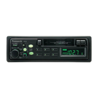
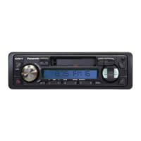
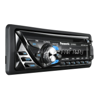
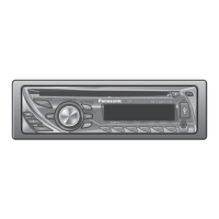
Identifies and describes all controls on the front panel of the unit.

RM-1100 Disassembly and Component Location

Disassembly Instructions and Views

Provides steps and diagrams for taking the unit apart.

Electrical Parts Locations

Shows the placement of electrical components on internal boards.

RM-1100 Disassembly Procedures

Component Removal Steps and Hardware

Details component removal steps and the hardware involved.

RM-1100 Harness Connections and Waveforms

Wiring Diagram Details

Illustrates the internal wiring connections of the unit.

Signal Waveform Analysis

Shows output signal timing and waveform characteristics.

RM-1100 Measurements and Adjustments

Alignment Procedures (AM, FM, Stereo, Azimuth)

Details the steps for aligning various sections of the tuner and deck.

Alignment Test Point Locations

Identifies specific test points for alignment procedures.

RM-1100 Alignment Procedures and Diagrams

FM RF and DC Balance Alignment Steps

Details alignment steps for FM RF and DC balance sections.

FM Stereo and Azimuth Alignment Steps

Details alignment steps for FM stereo and azimuth.

Alignment Test Point Diagrams

Provides diagrams showing test points for alignment.

RM-1100 Liquid Crystal Display (LCD)

LCD Connections and Timing Waveforms

Explains LCD connections, signal timing, and waveforms.

LCD Terminal Function Explanations

Details the function of each terminal on the LCD driver.

RM-1100 IC7 (RVITC9137 P) Details

IC7 Terminal View and Block Diagram

Shows the physical layout, block diagram, and connections of IC7.

IC7 Terminal Function Explanations

Details the function of each terminal on IC7.

RM-1100 Audio System Connection

System Block Diagram for Integration

Illustrates how the unit connects within an audio system.

RM-1100 IC Block Diagrams

Integrated Circuit Functional Blocks

Provides functional block diagrams for key integrated circuits.

RM-1100 Main Schematic Diagram

Main Circuit Overview

Presents the overall schematic of the main circuit board.

Main Circuit IC Component Mapping

Shows the location of integrated circuits on the main schematic.

RM-1100 Main Circuit Schematics

Detailed Main Circuitry Diagrams

Provides in-depth schematic diagrams of the main circuitry.

RM-1100 Main Circuit Board Layout

Main PCB Component Placement

Shows the placement of components on the main circuit board.

Electronic Component Symbols Reference

Illustrates common electronic component symbols used in diagrams.

RM-1100 AM and LCD Schematics and Boards

AM Circuit Diagram and PCB Layout

Shows the schematic and component layout for the AM section.

LCD Circuit Diagram and PCB Layout

Shows the schematic and component layout for the LCD driver.

RM-1100 Tape Deck and Power Source Schematics and Boards

Tape Deck Circuit Diagram and PCB Layout

Provides the schematic and component layout for the tape deck.

Power Source Circuit Diagram and PCB Layout

Provides the schematic and component layout for the power supply.

RM-1100 Tape Deck and Power Source Board Details

Tape Deck PCB Layout Diagrams

Shows component placement on the tape deck circuit board.

Power Source PCB Layout Diagrams

Shows component placement on the power source circuit board.

RM-1100 Tape EQ & Ambience Schematics and Boards

Tape EQ & Ambience Circuit Diagram and PCB Layout

Shows the schematic and component layout for tape EQ/ambience.

RM-1100 Wiring Connection Diagram

Inter-Circuit Board Wiring Connections

Illustrates the wiring between different circuit boards.

RM-1100 Wiring Diagrams Overview

Inter-Board Connection Schematics

Shows how various internal circuit boards are interconnected.

RM-1100 System Block Diagram

Overall Functional Block Overview

Depicts the overall functional flow and interaction of unit components.

RM-1100 Parts Location - Mechanism

Mechanical Component Breakdown Diagrams

Shows the location and identification of mechanical parts.

RM-1100 Parts Location - Cabinet

Chassis and Exterior Component Placement

Shows the location of cabinet and exterior parts.

RM-1100 Parts Location - Electrical

PCB Component Identification Diagrams

Shows the location of various electrical components on PCBs.

RM-1100 Electrical Parts Locations (Continued)

PCB Component Identification (Various Boards)

Continues showing component locations on different circuit boards.

RM-1100 Replacement Parts List - Mechanical

Mechanical Component Part Numbers and Descriptions

Lists all replaceable mechanical parts with their codes and descriptions.

RM-1100 Replacement Parts List - Electrical Components

ICs, Transistors, and Diodes Part Numbers

Lists part numbers for integrated circuits, transistors, and diodes.

Coils, Transformers, and Variable Components Part Numbers

Lists part numbers for coils, transformers, and variable components.

Switches and Cabinet Parts Part Numbers

Lists part numbers for switches and cabinet/exterior parts.

RM-1100 Replacement Parts List - Resistors

Resistor Part Numbers and Values

Lists all resistors with their part numbers and resistance values.

RM-1100 Replacement Parts List - Capacitors

Capacitor Part Numbers and Values

Lists capacitor part numbers and their capacitance values.

RM-1100 Replacement Parts List - Capacitors (Continued)

Capacitor Part Numbers and Values (Continued)

Lists additional capacitor part numbers and their values.

RM-1100 Replacement Parts List - Capacitors (Continued)

Capacitor Part Numbers and Values (Continued)

Lists final capacitor part numbers and their values.

RM-M1100 Power Amplifier Specifications

RM-M1100 Technical Specifications

Covers rated power, impedance, power source, consumption, dimensions, weight.

RM-M1100 Power Amplifier Disassembly and Parts Location

Disassembly Steps and Hardware

Outlines the process and hardware for disassembling the power amplifier.

Power Amplifier PCB Component Locations

Shows the placement of components on the power amplifier circuit boards.

RM-M1100 Power Amplifier Circuit Diagrams and Board Layouts

Power Amplifier Circuit Diagram

Provides the schematic diagram for the power amplifier unit.

Power Amplifier PCB Layout and Connections

Shows the circuit board layout and wiring connections for the power amplifier.

RM-M1100 Power Amplifier Replacement Parts

RM-M1100 Component Listing

Lists all replaceable components for the power amplifier unit.

RD-1103 Auto Volume Unit Specifications

RD-1103 Technical Specifications

Details power source, consumption, gain, control, dimensions, and weight.

RD-1103 Auto Volume Unit Controls and Disassembly

Control Panel Overview

Identifies controls and connections on the auto volume unit.

Disassembly Steps and Hardware

Outlines the process and hardware for disassembling the unit.

RD-1103 Auto Volume Unit Schematics and Board Layouts

RD-1103 Circuit Diagrams (FET Types)

Provides schematics for both one and two FET configurations of the unit.

RD-1103 PCB Layouts and Wiring

Shows circuit board layouts and wiring for the auto volume unit.

RD-1103 Auto Volume Unit Adjustments and Replacement Parts

Gain Alignment Procedure

Details the steps for performing gain alignment on the unit.

RD-1103 Component Listing

Lists all replaceable components for the auto volume unit.

RM-1100 Accessories - Radio Cassette and Power Amplifier

Radio Cassette Accessory Components

Details the parts included in the radio cassette accessory.

Power Amplifier Accessory Components

Details the parts included in the power amplifier accessory.

RM-1100 Accessories - Auto Volume and Head Set

Auto Volume Accessory Components

Details the parts included in the auto volume accessory.

Head Set Accessory Components

Details the parts included in the head set accessory.

RM-1100 Accessories - Junction Box

Junction Box Accessory Components

Details the parts included in the junction box accessory.

Related product manuals