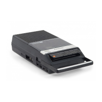
The Panasonic RQ-2720 is a portable cassette recorder with tape speed control, designed for various regions including Europe (excluding the UK), Asia, Latin America, the Middle East, and Africa. This service manual provides comprehensive details for its maintenance and repair.
Function Description:
The RQ-2720 is a 2-track monaural recording and playback device. Its primary function is to record and play back audio on standard C-60 cassette tapes, offering approximately 1 hour of program time. A key feature is its adjustable tape speed control during playback, fast forward, rewind, cue, and review operations, allowing for a range of about ±20% deviation from the standard speed. The recorder incorporates a pushbutton one-touch recording mechanism, along with cue, review, and auto-stop functions for user convenience.
Important Technical Specifications:
- Power Requirement: The unit operates on 3V, powered by two UM-3 size dry batteries. Its power consumption is 6W.
- Motor: An electronic governor motor ensures stable tape movement.
- Power Output: The maximum power output is 350 mW.
- Frequency Range: The device covers a frequency range of 100 to 10,000 Hz.
- Tape Speed: The standard tape speed is 4.8 cm/s (1-7/8 ips).
- Speaker: It features a 5 cm (2") PM dynamic speaker.
- Input:
- MIC: Sensitivity of 0.25 mV, compatible with microphones having an impedance of 200-600 Ω (the WM-2213 is recommended).
- DC IN: 3V.
- Output:
- Monitor: 8Ω.
- Remote: For start and stop control.
- Dimensions: 175mm (W) × 19.79mm (H) × 109mm (D) [6-7/8" (W) × 25/32" (H) × 4-9/32" (D)].
- Weight: 415g (15 oz), without batteries.
Usage Features:
The RQ-2720 is designed for ease of use with clearly labeled controls.
- Controls and Components:
- Built-in microphone: For direct audio recording.
- Tape counter and reset button: To track tape position and reset the counter.
- Cassette lid: For accessing the tape compartment.
- Pause switch: To temporarily stop recording or playback.
- Microphone sensitivity selector (LOW/HIGH): To adjust microphone input sensitivity.
- Recording indication lamp: Illuminates during recording.
- Battery check lamp: Indicates battery status.
- Hand strap: For portability.
- Playback tape speed control: A dedicated knob for adjusting playback speed.
- Stop/eject button: To stop tape movement and eject the cassette.
- Record button: For initiating recording.
- Playback button: For initiating playback.
- Review button: For quickly reviewing recorded audio.
- Cue button: For quickly cueing forward.
- External microphone jack: For connecting an external microphone.
- Remote control jack: For connecting a remote control to start/stop the device.
- Monitor jack: For connecting headphones to monitor audio.
- Volume control: To adjust output volume.
- Battery-case-removal knob and Battery case: For battery access.
- AC adaptor jack (DC IN 3V): For external power supply.
- Speaker Monitor Muting During Recording: To prevent acoustic feedback (howling), the built-in speaker is automatically muted during recording. However, if earphones are inserted into the monitor jack, the muting is overridden, allowing monitoring through the earphones with adjustable volume.
- Constant Speed Control: The motor employs a bridge servo system to maintain constant tape speed during operation.
- Tape Speed Control in Playback Mode: A dedicated control (VR101) allows for approximately ±20% adjustment of tape speed during playback. This function is disabled during record mode.
- Safety Timer Function: In fast forward (FF) or rewind (REW) modes, if the STOP button is not pressed after the tape is fully reeled, a safety timer activates to stop the motor after about 6 minutes. This prevents excessive battery consumption and mechanical strain, especially important for a low-voltage (3V) device.
- Auto-Stop Mechanism: The device features a mechanical auto-stop function that activates when the tape is fully reeled up in PLAY or REC/PLAY modes. This function does not operate in FF, REW, CUE, and REVIEW modes, where the STOP button must be used manually.
- Pause Function: The PAUSE switch electrically stops the motor and safety timer circuit, effectively pausing operation. This switch also controls FF and REW operations.
Maintenance Features:
The service manual provides detailed instructions for disassembly, mechanical removal, chip repair, and various adjustments.
- Disassembly Instructions: Step-by-step guide for removing the bottom case, main case assembly, and circuit board, specifying the number of screws and soldered points involved.
- Mechanical Removal:
- Chassis Cover Removal: Instructions for detaching the erase safety lever spring and removing set screws to detach the chassis cover.
- Head Base Plate Removal: Details on removing set screws and a stop ring to detach the push button unit and head base plate.
- Lower Base Plate Removal: Instructions for removing the flywheel belt cover, snap rings from reel tables, set screws, and detaching the lock release lever spring to remove the lower base plate.
- Chip Repair Procedure:
- Removal: Guidance on using a solder sucker and tweezers to remove chips, emphasizing the importance of turning off the unit and checking resistance/polarity.
- Mounting: Instructions for applying solder and mounting chips, recommending a pencil-type soldering iron and temperature control (under 260°C/500°F). It also highlights precautions like not heating chips beyond 3 seconds, avoiding rubbing electrodes, using tweezers to prevent damage, and not reusing tantalum, hall, or ceramic capacitors.
- IC Mounting: Specific instructions for replacing the IC2 (M51503L), including cutting its pins as illustrated.
- Measurement and Adjustment Methods:
- Head Azimuth Adjustment: Procedure for adjusting the record/playback head angle using a test tape (QZZCFM 8kHz), VTVM, and oscilloscope to achieve maximum output level.
- Tape Speed Accuracy Adjustment: Method for adjusting tape speed using a test tape (QZZCWAT 3,000 Hz) and a digital electronic counter, aiming for a frequency of 3,000 Hz (±2.5% accuracy).
- Bias Current Adjustment: Procedure for adjusting bias current in record mode using a VTVM and oscilloscope, targeting a standard value of 0.5±0.05mA.
- Battery Check Circuit Adjustment: Instructions for adjusting the battery check indicator circuit (VR2) by setting DC supply voltage to 2.07V and regulating VR2 to turn the LED on/off.
- Safety Timer Circuit Adjustment: Method for checking and adjusting the safety timer circuit (VR103) in fast forward mode, ensuring the motor stops within 6±1.5 minutes (general check) or 8.5±2 seconds (early check with 220 kΩ resistor in parallel with R122).
- Electrical Parts Location: Detailed diagrams showing the placement of various electrical components on the circuit board, including ICs, transistors, resistors, capacitors, diodes, and switches, along with their reference numbers.
- Wiring Connection Diagram: Comprehensive diagrams illustrating the wiring connections between different components, including the motor, battery terminals, jacks, switches, and the main circuit board, with color codes for wires.
- Exploded Views and Mechanical Parts Location: Detailed diagrams showing the exploded view of the device and the location of various mechanical parts, including gears, springs, levers, and the motor, with part numbers and descriptions.
- Spring Location: Specific diagrams detailing the location and function of various springs within the mechanism, such as the erase safety lever spring, cassette pressure spring, auto-stop detection lever spring, and brake arm springs.
- Cabinet Parts: Listing of all cabinet components with part numbers and descriptions, categorized by region (European areas except UK, and Asia/Latin America/Middle East/Africa areas).
The manual also includes a list of accessories and packing information.