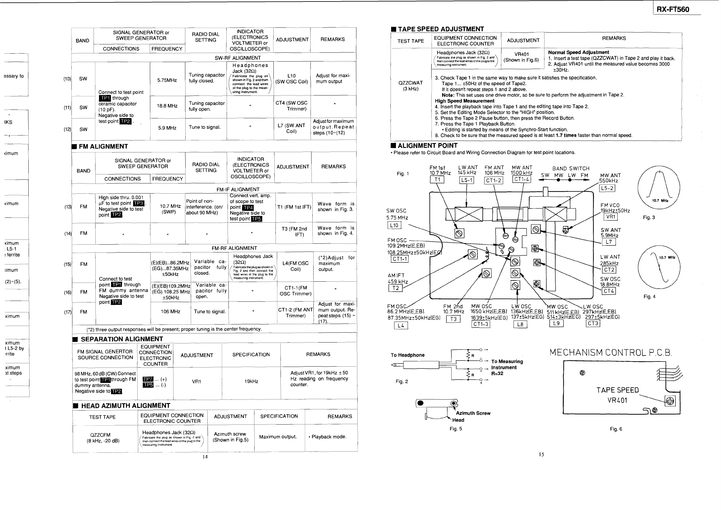
TAPE SPEED ADJUSTMENT
-
I
I
1
EQUIPMENT CONNECTION
ADJUSTMENT
1
1
TEST
TAPE
1
ELECTRONIC COUNTER
1
SIGNAL GENERATOR or
1
BAND
SWEEP GENERATOR REMARKS
RADIO
DIAL INDICATOR
VOLTMETER
or
1
1
CONNECTIONS FREQUENCY
1
/
OSCILLOSCOPE)
1
1
I
!
Headphones Jack (32R)
Normal Speed Adjustment
Fabricate the plug
as
shown
In
Flg.
2
and
thencon"edIheleadwiresollhepluglothe
1. Insert a test tape (QZZCWAT) in Tape 2 and play it back.
measuring
instrument.
2. Adjust VR401 until the measured value becomes 3000
r
-
SW-RF ALIGNMENT
I
1
I I I
Headohones
I I I
Tuning capacitor
1
(
Fabricate
~~~~i~~~~)andIhen
the
plug
as
1
LIO
ldjust for maxi-
5.75MHz
1
fully closed.
connect
the
lead
wires
1
,
(SW OSC 'Oil)
mum
Output
essary to
j
QZZCWAT
(3 kHz)
3. Check Tape
1
in
the same way to make sure it satisfies the specification.
Tape 1
...
+50Hz of the speed of Tape2.
If it doesn't repeat steps 1 and 2 above.
Note:
This set uses one drive motor, so be sure to perform the adjustment in Tape 2.
High Speed Measurement
4. Insert the playback tape into Tape 1 and the editing tape into Tape 2.
5. Set the Editing Mode Selector to the "HIGH" position.
6.
Press the Tape 2 Pause button, then press the Record Button.
7. Press the Tape 1 Playback Button.
Editing is started by means of the Synchro-Start function.
8. Check to be sure that the measured speed is at least
1.7
times
faster than normal speed.
W
0
1st pi
1
\:::it%::
meas-/
1
1
,,
through
ceramic capacitor
8,8
MHz
Tuning capacitor CT4 (SW OSC
(11) (1 0 PF). fully open. Trimmer)
ALIGNMENT POINT
Please refer to Circuit Board and Wiring Connection Diagram for test point locations.
SIGNAL GENERATOR or INDICATOR
SWEEP GENERATOR
RADIO DIAL (ELECTRONICS
I
BAND
I
,
SETING VOLTMETER or
FM 1st
LW
ANT
FM
ANT
MW
ANT BAND
SWITCH
10.7 MHz
145kHz 106 MHz
1500kHz
SW
MW
LW
FM
MW
ANT
CONNECTIONS FREQUENCY
1
OSCILLOSCOPE)
FM-IF ALIGNMENT
(13)
Fig. 3
:
L5-1
!
ferrite
I
'-'-'
FM-RF ALIGNMENT
('2)Adjust for
L4(FM OSC
1
maximum
"j
coil) output.
1
Connect to test
point through
(E)(EB)~ 09.2~~~ Variable ca-
FM dummy antenna (EG) 108.25
MHZ
pacitor fully
Negative side to test open.
OSC Trimmer)
k50kHz
Fig. 4
FM
OSC/
FM
26d
MW
osc
La
osc
'MW
OSC
\LW
OSC
86.2
MHz(E,EB).
10.7 MHz 1650 kHz(E,,EB) 136kHzlE.EB) 511 kHz(E,EB) 297kHz(E,EB)
~~,~~MH~~~O~H~(EGJ
1639_+5kHz(EG) 13725kHz(EGI 51423kHzlEG) 297?5kHz(EG)
El
pLq
pJ
m
1
106 MHz Tune to signal.
(
I
1
1
_____I
I
(17).
('2) three output responses
w~ll be present; proper tun~ng is the center frequency.
SEPARATION ALIGNMENT
REMARKS
98 MHz, 60dB (CW) Connect
AdjustVRl ,for 19kHz k50
1
to test pointmthrough FM
...
(+)
I
19kHz
Hz reading on frequency
dummy antenna.
...
(-)
counter.
I
j
Negative side tom
----.--A-
HEAD AZIMUTH ALIGNMENT
111_-
7
To Headphone
-
To Measuring
-
Instrument
R=32
Fig. 2
MECHANISM CONTROL P.C.B
ximum
it steps
TAPE
SPEED
,";muth Screw
Fig. 5
1
TEST TAPE IEQUlPMENT CONNECTION
I
--
1
ELECTRONIC COUNTER
I
r
--
7-
Fig. 6
QZZCFM
1
Headphones Jack (320)
Fabr~cale the plug
as
shown
I"
Fig.
2
and
Azimuth
screw
Maximum output.
(8
kHz, -20 dB)
then connect thelead wiresollhepiugla lhe
measuring instrumenl.