EasyManua.ls Logo

Panasonic RX-FS400 User Manual

Panasonic RX-FS400
14 pages
To Next Page IconTo Next Page
Page #1 background imageLoading...
Page #1 background image
ORDER
NO.
MD8907033A4
ervice
MVianual
Radio
Cassette
Stereo
Radio
Cassette
Recorder
R
x
E
S
400
e
Please
file
and
use
this
Service
Manual
together
with
the
service
manual
for
Model
No.
RX-FS400
Order
No.
MD8901001C1
e
This
Service
Manual
indicates
the
main
differences
between;
Original
RX-FS400
[for
(P)
mark
area]
and
RX-FS400
(PX).
|
(K)
oltaaes
Black
Type
Area
Country
CHANGES
Europe-PX
—————
os
Far
East-PX
be
=
SPECIFICATIONS
General:
General:
Power
Requirement:
AC;
120
V,
60
Hz
Power
Requirement:
AC;
110~127
V
200~
220V
=p
230~250V
50/60
Hz
Power
Consumption:
13
W
(AC
only)
Power
Consumption:
15
W
(AC
only)
Weight:
(2.3
kg)
without
batteries
Weight:
(2.2
kg)
without
batteries
RX-FS400
(P)
(Original)
RX-FS400
(PX)
=
PARTS
COMPARISON
TABLE
Notes:
1.
Important
safety
notice:
Components
identified
by
/A\
mark
have
special
characteristics
important
for
safety.
When
replacing
any
of
these
components
use
only
manufacturer’s
specified
parts.
2.
[M]
Indicates
parts
that
are
supplied
by
MESA.
Parts
Number
Ref.
No.
Description
|
RX-FS400
(P)
Remarks
CAPACITOR
C316
CAPACITOR,
220uF,
16V
ECEAICV221SE
ECEA1CU221B
Changed
C114,
214,
:
312,
320
CAPACITOR,
0.01
uF,
50V
ECKD1H1032ZF
ECKT1H103MD
Changed
INTEGRATED
CIRCUITS
CABINET
AND
CHASSIS
POWER
PCB
IW
i
swage
[VOLTAGE
SELECTOR
sd
SSC*RGADZAH
Acces
TRANSFORMER
ACCESSORIES
1
Panasonic
Matsushita
Electric
Industrial
Co.,
Ltd.
®
Central
P.O.
Box
288,
Osaka
530-91,
Japan
Question and Answer IconNeed help?

Do you have a question about the Panasonic RX-FS400 and is the answer not in the manual?

Panasonic RX-FS400 Specifications

General IconGeneral
BrandPanasonic
ModelRX-FS400
TypeCassette Player
Power SourceAC/DC
FeaturesAM/FM Radio
Wow and Flutter0.18% (WRMS)

Summary

Specifications Overview

General Power and Consumption Details

Details AC power requirements, consumption, and weight for RX-FS400 (P) and RX-FS400 (PX) models.

Parts Comparison Table

Lists component differences and part number changes between RX-FS400 (P) and RX-FS400 (PX) models.

Power Supply Circuitry

Power Supply Schematics

Schematics for the power supply circuit of RX-FS400 (P) and RX-FS400 (PX) models.

Circuit Board Wiring Diagrams

Wiring connection diagrams for the power supply PCB for both RX-FS400 (P) and RX-FS400 (PX) models.

Cabinet Parts Location

Illustrates the location of key components like the transformer and voltage selector on the power PCB.

Mechanism Series Specifications

General and Power Specs

Details general, power requirement, consumption, and output specifications for the mechanism series.

Speaker, Dimensions, and Weight

Lists speaker details, physical dimensions, and weight for the RX-FS400 mechanism series.

Radio and Tape Deck Specs

Covers radio frequency range, intermediate frequency, sensitivity, and tape deck performance metrics.

Safety and Controls

Safety Precautions and Testing

Essential safety guidelines for servicing and insulation resistance testing procedures.

Controls and Components Identification

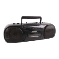
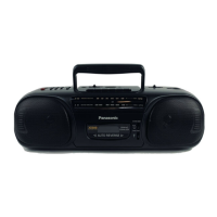
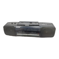
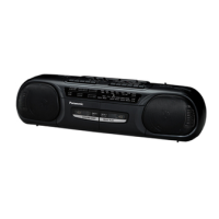
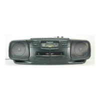
Identification of front panel controls, indicators, and external components.

Battery Service Life

Information on estimated battery life for recording and playback operations.

Disassembly Procedures

External and Major Component Removal

Instructions for removing the front cabinet, speaker, LED PCB, and main PCB.

Internal Component Disassembly

Steps for removing the dial chassis, mechanism, record lever, and tuner PCB.

Antenna and Power Circuit Removal

Guide to disassembling the antenna PCB and power PCB components.

Advanced Disassembly and Assembly

Cassette Compartment and Battery Parts

Procedures for removing the cassette compartment and battery terminal/PCB.

Dial Chassis and Record Lever Assembly

Instructions for assembling the dial chassis and record lever mechanisms.

Schematic Diagrams

Tuner and Antenna Circuits

Detailed schematic of the tuner and antenna sections, including ICs and component connections.

Main, LED, and Power Circuits

Schematics for the main circuit, LED indicator, and power supply systems.

Circuit Board and Wiring Diagrams

Tuner and Antenna PCB Layout

Wiring diagram and component layout for the tuner and antenna PCBs.

Main and LED PCB Layout

Wiring diagram and component layout for the main and LED circuit boards.

Power Supply PCB Layout

Wiring diagram and component layout for the power supply circuit board.

Measurements and Adjustments

General Alignment Setup

Essential instructions and setup steps prior to performing alignment procedures.

FM and AM Alignment Procedures

Detailed steps for FM-IF, FM-RF, and AM-IF/RF signal alignments.

Tape Speed and Head Azimuth Adjustment

Procedures for adjusting tape speed and head azimuth for optimal playback.

Replacement Parts List

Cabinet, Chassis, and Integrated Circuits

List of replacement parts for cabinets, chassis, and integrated circuits.

Transistors, Diodes, Coils, and Filters

Replacement parts list for transistors, diodes, coils, transformers, and filters.

Mechanism and Accessories

Replacement parts for the mechanism, accessories, and packing materials.

Mechanism Parts Location

Mechanism Component Layout

Diagram illustrating the location of various components within the mechanism assembly.

Spring Illustration

Illustrations showing the actual size and shapes of springs for identification.

Cabinet Parts Location Diagram

Exploded View of Cabinet Components

An exploded view showing the location of cabinet parts and their assembly points.

Resistors & Capacitors Reference

Resistor Numbering System

Explanation of the numbering system used for resistors, including type, wattage, and tolerance.

Capacitor Numbering System

Explanation of the numbering system for capacitors, including type, voltage, and value.

Component Values List

Detailed list of resistor and capacitor part numbers, values, and voltage ratings.

Related product manuals