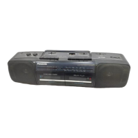
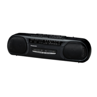
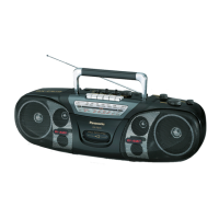
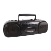
Do you have a question about the Panasonic RX-FT560 and is the answer not in the manual?
General specifications covering power, weight, dimensions.
Radio frequency ranges for FM, MW, SW, LW.
Intermediate frequencies and sensitivity ratings for radio bands.
Tape deck specifications including frequency response and speed.
Detailed listing and identification of all operational controls, inputs, and indicators.
Step-by-step guide to remove the unit's handle.
Step-by-step guide to remove the front cabinet.
Step-by-step guide to remove the speaker units.
Step-by-step guide to remove the cassette compartment assembly.
Step-by-step guide to remove the dial chassis assembly.
Step-by-step guide to remove the tuning pointer.
Step-by-step guide to remove the tape mechanism unit.
Step-by-step guide to remove the graphic equalizer printed circuit board.
Step-by-step guide to remove the graphic equalizer chassis and its knobs.
Step-by-step guide to remove the main printed circuit board.
Step-by-step guide to remove the battery printed circuit board.
Step-by-step guide to remove the power supply printed circuit board.
Step-by-step guide to remove the battery spring.
Step-by-step guide to remove the tuner printed circuit board.
Step-by-step guide to remove the mechanism printed circuit board.
Step-by-step guide to remove the varicon gear.
Step-by-step guide to remove the tuning knob.
Step-by-step instructions for correctly assembling the dial chassis.
Schematic diagram illustrating the tuner printed circuit board layout.
Identification guide for integrated circuits, transistors, and diodes used in the circuit.
Schematic diagram illustrating the main printed circuit board.
Schematic diagram illustrating the graphic equalizer circuit.
Schematic diagram illustrating the LED indicator circuit.
Schematic diagram illustrating the power supply circuit.
Circuit board layout and wiring connections for the tuner PCB.
Circuit board layout and wiring for FM mode/B.P and selector controls.
Circuit board layout and wiring for the graphic equalizer PCB.
Circuit board layout and wiring for the main PCB.
Circuit board layout and wiring for the power supply PCB.
Circuit board layout and wiring for the LED indicator PCB.
General instructions and precautions before starting alignment procedures.
Alignment procedures for LW, MW, and SW radio bands.
Alignment procedures for the FM radio band.
Procedure for adjusting audio channel separation in the FM signal.
Procedure for adjusting the tape head azimuth for optimal playback.
Specific RF alignment steps for the SW radio band.
Specific IF alignment steps for the FM radio band.
Specific RF alignment steps for the FM radio band.
Procedure for adjusting the tape playback speed for both decks.
Reference guide for test point locations used in alignment procedures.
Exploded view and part identification for the Deck 1 mechanism.
Exploded view and part identification for the Deck 2 mechanism.
Diagram showing the locations of various springs within the mechanism.
Visual representation of spring shapes and sizes for mechanism assembly.
List of transistors, diodes, and LEDs with part numbers and types.
List of variable capacitors, trimming capacitors, and fuses with part numbers.
List of coils, transformers, integrated circuits, and switches with part numbers.
Exploded view and part identification for cabinet and chassis components.
List of resistors with their reference numbers, values, and part numbers.
List of capacitors with their reference numbers, values, and part numbers.
| Brand | Panasonic |
|---|---|
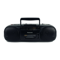
| Model | RX-FT560 |
| Speakers | 2 speakers |
| Power Supply | AC |
| Battery type | 6 x D |
| Tuner | FM |
| Tape deck | Single |
| Output Power | 2.5W |