EasyManua.ls Logo

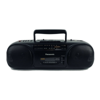
Panasonic RX-DT30 User Manual

Panasonic RX-DT30
40 pages
To Next Page IconTo Next Page
Page #1 background imageLoading...
Page #1 background image
ORDER NO. MD9502012C1
Service
Manual
Portable Stereo CD System
MASH*
Radio Cassette
RX-DT30
Colour
TAPE DECK
: SG-20W MECHANISM SERIES
TRAVERSE DECK : RAE01 13Z MECHANISM SERIES
I
SPECIFICATIONS
n
Radio Section
Frequency range
FM
AM
Intermediate frequency
FM
AM
Sensitivity
FM
AM
H CD Player
Sampling frequency
Decoding
Beam source
No. of channels
Wow and flutter
D/A
converter
88-108MHz
525
-
1705
kHz
10.7 MHz
455
kHz
17
dB/50
mW
(
-3
dB
limit sens.
)
51
dB/m/50
mW
44.1
kHz
16 bit
Iinear
Semiconductor laser
(wavelength 780 nm)
2 channel, stereo
Less than possible measurement data
MASH (1 bit DAC)
Panasonic”
/
(K) Black Type 1
n
Tape Recorder
Track system
Recording system
Erasing system
Monitor system
Frequency range
Normal
n
General
4 track, 2 channel, stereo
AC bias
Multi
pole magnet
Variablesoundmonitor
50
-
14000 Hz
Power requirement
AC
120V, 60Hz
Power consumption; 30W
Battery
12 V (8
“D”
size, R20/LR20 batteries)
Speakers
10 cm (4”) x 2
Jacks
Output
Headphones;
32c1
Dimensions (W x H x D)
580x192
x260mm
(22’3/~s”x79/~6”x1
01/4”)
Weight
4.5 kg (9 lb.
15
oz.)
without batteries
Notes
:
Specifications are subject to change without notice.
Weight
and
dimensions are approximate.
©
1995 Matsushita Electronics (S) Pte. Ltd.
All rights reserved. Unauthorized copying and
distribution is a violation of law.
Question and Answer IconNeed help?

Do you have a question about the Panasonic RX-DT30 and is the answer not in the manual?

Panasonic RX-DT30 Specifications

General IconGeneral
BrandPanasonic
ModelRX-DT30
TunerFM/AM
CD PlayerYes
Cassette Decks1
Speakers2 Speakers
Frequency Response20 Hz - 20 kHz

Summary

Specifications

Radio Section

Details of FM/AM reception characteristics.

CD Player

Specifications for the CD playback mechanism.

Tape Recorder

Features and range of the cassette tape recorder.

General

Power requirements, dimensions, and weight of the unit.

Disassembly Instructions

Removal of the Handle

Steps to detach the carrying handle from the unit.

Removal of the Front Cabinet

Procedure to remove the front casing panel.

Removal of the Top Cabinet Unit

Steps to detach the upper housing cover.

Removal of the Control P.C.B.

Instructions for removing the main control board.

Removal of the Connector P.C.B.

Steps to detach the connector printed circuit board.

Removal of the Mechanism Unit

Procedure for removing the tape/CD mechanism assembly.

Removal of the Traverse Unit

Steps to detach the CD traverse mechanism.

Removal of the Main P.C.B.

Instructions for removing the primary circuit board.

Removal of the Power Supply P.C.B.

Steps to detach the power supply circuit board.

Removal of the CD Cover

Steps to remove the CD compartment lid.

Removal of the Disc Clamp Unit

Instructions for detaching the CD disc clamping mechanism.

Removal of the Speakers

Steps to detach the audio speaker units.

Removal of the Cassette Compartment

Procedure to remove the cassette tape housing.

Removal of the Servo P.C.B.

Steps to detach the servo control circuit board.

Maintenance and Troubleshooting

How to Check Traverse Unit

Procedure for checking the CD traverse unit operation.

Tape Entanglement Resolution

Steps to fix tape caught in the pitch roller mechanism.

Component Identification

Terminal Guide of ICs, Transistors & Diodes

Pin assignments and functions for various electronic components.

Schematic Diagrams

Servo Circuit Diagram

Detailed schematic for the CD servo control system.

Main Circuit Diagram

Schematic of the primary electronic components and connections.

Tuner Circuit Diagram

Schematic detailing the FM/AM radio tuning section.

Control Circuit Diagram

Schematic for the system control and user interface logic.

GEQ Circuit Diagram

Schematic of the graphic equalizer and related audio circuits.

Power Supply Circuit Diagram

Schematic showing the power distribution and regulation.

Wiring and Connections

Wire Connection Diagram

Visual guide illustrating how wires connect PCBs and components.

Printed Circuit Board Layouts

Servo P.C.B. Layout

Component placement and routing for the servo board.

Deck P.C.B. Layout

Component placement and routing for the deck control board.

Main P.C.B. Layout

Component placement and routing for the main system board.

Power Supply P.C.B. Layout

Component placement and routing for the power supply board.

Tuner P.C.B. Layout

Component placement and routing for the tuner board.

IC Pin Function Details

IC702 Terminal Functions

Detailed pin assignments for the MN66271 RA processor.

IC701 Terminal Functions

Detailed pin assignments for the AN8802SCE1 V servo amplifier.

IC801 Terminal Functions

Detailed pin assignments for the M38222M2051 microprocessor.

IC703 Terminal Functions

Detailed pin assignments for the AN8389SE1 driver IC.

Measurements and Adjustments

Tuner Section Alignment

Procedures for aligning AM-IF, AM-RF, FM-IF, and FM-RF stages.

Cassette Deck Section Alignment

Instructions for tape speed adjustment for decks 1 and 2.

CD Player Mechanical Adjustment

Steps for adjusting RF signal and eye pattern.

Mechanism Parts Information

Mechanism Parts List

Comprehensive list of replacement parts for the cassette mechanism.

Mechanism Parts Location

Diagrams showing the physical location of parts for Deck 1.

Cabinet Assembly

Cabinet Parts Location

Diagrams illustrating the placement of cabinet components.

Troubleshooting Guide

No CD Playback Troubleshooting

Flowchart for diagnosing CD playback issues.

Optical Pickup Issues

Troubleshooting steps for optical pickup movement and signal.

Replacement Parts List

Cabinet and Chassis Parts

List of parts for the outer casing and structural elements.

Integrated Circuits

List of ICs used in the unit with their functions.

Transistors

List of transistors used in the unit.

Diodes

List of diodes used in the unit.

Switches

List of user-operable switches and their functions.

Coils & Transformers

List of inductor and transformer components.

Fuses and Connectors

Fuses and Fuse Holders

Details on fuses and their respective holders.

Connectors

List of connectors and their pin configurations.

Chip Jumpers

Information on chip jumpers used for configuration.

Related product manuals