Do you have a question about the Panasonic RX-DT30 and is the answer not in the manual?
| Brand | Panasonic |
|---|---|
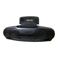
| Model | RX-DT30 |
| Tuner | FM/AM |
| CD Player | Yes |
| Cassette Decks | 1 |
| Speakers | 2 Speakers |
| Frequency Response | 20 Hz - 20 kHz |
Details of FM/AM reception characteristics.
Specifications for the CD playback mechanism.
Features and range of the cassette tape recorder.
Power requirements, dimensions, and weight of the unit.
Steps to detach the carrying handle from the unit.
Procedure to remove the front casing panel.
Steps to detach the upper housing cover.
Instructions for removing the main control board.
Steps to detach the connector printed circuit board.
Procedure for removing the tape/CD mechanism assembly.
Steps to detach the CD traverse mechanism.
Instructions for removing the primary circuit board.
Steps to detach the power supply circuit board.
Steps to remove the CD compartment lid.
Instructions for detaching the CD disc clamping mechanism.
Steps to detach the audio speaker units.
Procedure to remove the cassette tape housing.
Steps to detach the servo control circuit board.
Procedure for checking the CD traverse unit operation.
Steps to fix tape caught in the pitch roller mechanism.
Pin assignments and functions for various electronic components.
Detailed schematic for the CD servo control system.
Schematic of the primary electronic components and connections.
Schematic detailing the FM/AM radio tuning section.
Schematic for the system control and user interface logic.
Schematic of the graphic equalizer and related audio circuits.
Schematic showing the power distribution and regulation.
Visual guide illustrating how wires connect PCBs and components.
Component placement and routing for the servo board.
Component placement and routing for the deck control board.
Component placement and routing for the main system board.
Component placement and routing for the power supply board.
Component placement and routing for the tuner board.
Detailed pin assignments for the MN66271 RA processor.
Detailed pin assignments for the AN8802SCE1 V servo amplifier.
Detailed pin assignments for the M38222M2051 microprocessor.
Detailed pin assignments for the AN8389SE1 driver IC.
Procedures for aligning AM-IF, AM-RF, FM-IF, and FM-RF stages.
Instructions for tape speed adjustment for decks 1 and 2.
Steps for adjusting RF signal and eye pattern.
Comprehensive list of replacement parts for the cassette mechanism.
Diagrams showing the physical location of parts for Deck 1.
Diagrams illustrating the placement of cabinet components.
Flowchart for diagnosing CD playback issues.
Troubleshooting steps for optical pickup movement and signal.
List of parts for the outer casing and structural elements.
List of ICs used in the unit with their functions.
List of transistors used in the unit.
List of diodes used in the unit.
List of user-operable switches and their functions.
List of inductor and transformer components.
Details on fuses and their respective holders.
List of connectors and their pin configurations.
Information on chip jumpers used for configuration.