ȖȯȠȘȕȥȦȟȝ
ǏǕǕǑǗǓǔǤ
PORTUGUÊS
NEDERLANDS
ITALIANO DEUTSCH ESPAÑOL FRANÇAIS ENGLISH
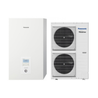
Air-to-Water Heatpump
■
R410A Models
Model No.
Indoor Units
Type Indoor Unit Type
Rated Capacity
80 125
W1 Air-to-Water
S-80MW1E5 S-125MW1E5
ENGLISH
Read through the Installation Instructions before you proceed with the installation.
In particular, you will need to read under the “IMPORTANT!” section at the top of the page.
FRANÇAIS
Lisez les instructions d’installation avant de commencer l’installation.
En particulier, vous devez lire la section “IMPORTANT!” en haut de la plage.
ESPAÑOL
Lea las Instrucciones de instalación antes de proceder con la instalación del equipo.
En concreto, deberá leer detenidamente la sección “¡IMPORTANTE!” situada al principio de la página.
DEUTSCH
Lesen Sie die Einbauanleitung, bevor Sie mit der Installation beginnen.
Insbesondere die Hinweise im Abschnitt “WICHTIG!” oben auf der Seite müssen unbedingt gelesen werden.
ITALIANO
Leggere le Istruzioni di installazione prima di procedere con l’installazione.
Prestare particolare attenzione alla sezione “IMPORTANTE!” all’inizio della pagina.
NEDERLANDS
Lees de installatie-instructies zorgvuldig door voor u begint met de installatie.
U moet vooral het gedeelte waar “BELANGRIJK!” boven staat heel goed lezen.
PORTUGUÊS
Leia cuidadosamente as instruções de instalação antes de prosseguir com a instalação.
Em particular, é necessário ler as informações na secção “IMPORTANTE!” na parte superior da página.
ǏǕǕǑǗǓǔǤ
ǎǶǭǮȉȀȁDZȁǶǿǙǰdzǯȌDZǿDZǯǷǭȁȉȀȁǭȀdzǿǽǾǶǺȀȂǺDZȅȌȀDZȁDZǹDZȁdzǺDZǯǷǭȁȉȀȁǭȀdzƔ
ǜȂǯǷDZǷǾǶǹȊǺǭƑǴǭȅǾDZǶǭȀȁDZȌǺǭǰǶǭǮȉȀDZȁDZȁdzǺDZǺȏȁdzȁǭƩǜǑǖNjǗǝǓǔǙƘƪȀȁǼǽȉǺȇǹȊǾǼǿȁdzǿȀDZǸȌǰǭǿƔ
ȖȯȠȘȕȥȦȟȝ
ȤəɗɠɎɛɎɛɎɑɖɚɛəɜɓɟɑɑɛɎɐɉɑɖɚɛɉɔɑəɉɖɎɘəɎɍɑɍɉɘəɗɍɣɔɏɑɛɎɚɑɖɚɛɉɔɑəɉɖɎɛɗƔ
ȗɠɉɚɛɖɗɚɛƑɢɎɛəɨɊɋɉɍɉɘəɗɠɎɛɎɛɎəɉɐɍɎɔɉƤȗȕțȢȣƘơɋɌɗəɖɉɛɉɠɉɚɛɖɉɚɛəɉɖɑɟɉɛɉƔ
for Refrigerant R410A
INSTALLATION INSTRUCTIONS
F616843
00_271229_aLL.indb 12015-7-28 11:09:14