EasyManua.ls Logo

Panasonic S*C09*3E8 Series User Manual

Panasonic S*C09*3E8 Series
440 pages
To Next Page IconTo Next Page
Page #1 background imageLoading...
Page #1 background image
1
ENGLISH
ENGLISH ................1
ESPAÑOL ............. 32
ITALIANO ..............63
SAFETY PRECAUTIONS
Read the following “SAFETY PRECAUTIONS” carefully before installation.
Electrical work must be installed by a licensed electrician. Be sure to use the correct rating and main circuit for the model to be installed.
The caution items stated here must be followed because these important contents are related to safety. The meaning of each indication
used is as below. Incorrect installation due to ignoring of the instruction will cause harm or damage, and the seriousness is classifi ed by the
following indications.
Please leave this installation manual with the unit after installation.
WARNING
This indication shows the possibility of causing death or serious injury.
CAUTION
This indication shows the possibility of causing injury or damage to properties only.
The items to be followed are classifi ed by the symbols:
Symbol with white background denotes item that is PROHIBITED from doing.
Symbol with dark background denotes item that must be carried out.
Carry out test run to confi rm that no abnormality occurs after the installation. Then, explain to user the operation, care and maintenance as
stated in instructions. Please remind the customer to keep the operating instructions for future reference.
WARNING
Do not use unspecifi ed cord, modifi ed cord, joint cord or extension cord for power supply cord. Do not share the single outlet with other electrical
appliances. Poor contact, poor insulation or over current will cause electrical shock or fi re.
Do not tie up the power supply cord into a bundle by band. Abnormal temperature rise on power supply cord may happen.
Keep plastic bag (packaging material) away from small children, it may cause suffocation.
Do not use pipe wrench to install refrigerant piping. It might deform the piping and cause the unit to malfunction.
Do not purchase unauthorized electrical parts for installation, service, maintenance and etc.. They might cause electrical shock or fi re.
Do not modify the wiring of Indoor Unit for installation of other components (i.e. heater, etc). Overloaded wiring or wire connection points may
cause electrical shock or fi re.
Do not add or replace refrigerant other than specifi ed type. It may cause product damage, burst and injury etc.
Do not use joint cable for Indoor / Outdoor Unit connection cable. Use specifi ed Indoor / Outdoor Unit connection cable, refer to instruction 6
CONNECT THE CABLE TO THE INDOOR UNIT and connect tightly for Indoor / Outdoor Unit connection. Clamp the cable so that no external
force will be acted on the terminal. If connection or fi xing is not perfect, it will cause heat up or fi re at the connection.
For electrical work, follow local wiring standard, regulation and this installation instruction. An independent circuit and single outlet must be used.
If electrical circuit capacity is not enough or defect found in electrical work, it will cause electrical shock or fi re.
For water circuit installation work, follow to relevant European and national regulations (including EN61770) and local plumbing and building
regulation codes.
Engage dealer or specialist for installation. If installation done by the user is defective, it will cause water leakage, electrical shock or fi re.
This is a R410A model, when connecting the piping, do not use any existing (R22) pipes and fl are nuts. Using such same may cause abnormally
high pressure in the refrigeration cycle (piping), and possibly result in explosion and injury. Use only R410A refrigerant.
Thickness for copper pipes used with R410A must be 0.8mm or more. Never use copper pipes thinner than 0.8mm.
It is desirable that the amount of residual oil is less than 40mg/10m.
When install or relocate Indoor Unit, do not let any substance other than the specifi ed refrigerant, e.g. air etc. mix into refrigerant cycle (piping).
Mixing of air etc. will cause abnormal high pressure in refrigeration cycle and result in explosion, injury etc.
Required tools for Installation Works
1 Phillips screw driver
2 Level gauge
3 Electric drill
4 Spanner
5 Pipe cutter
6 Reamer
7 Knife
8 Gas leak detector
9 Measuring tape
10 Megameter
11 Multimeter
12 Torque wrench
42 N•m (4.2 kgf•m)
65 N•m (6.5 kgf•m)
Installation Manual
AIR-TO-WATER HEATPUMP INDOOR UNIT
S*C09*3E8, S*C12*9E8, S*C16*9E8
ACXF60-03130
1
4
ACXF60-03130_EN ES IT.indb 1ACXF60-03130_EN ES IT.indb 1 9/22/2016 4:21:23 PM9/22/2016 4:21:23 PM
Question and Answer IconNeed help?

Do you have a question about the Panasonic S*C09*3E8 Series and is the answer not in the manual?

Panasonic S*C09*3E8 Series Specifications

General IconGeneral
BrandPanasonic
ModelS*C09*3E8 Series
CategoryHeat Pump
LanguageEnglish

Summary

Installation and Safety

Required Tools for Installation

Lists the necessary tools for performing the installation of the unit.

Safety Precautions

Details critical safety guidelines and warnings to follow during installation.

Unit Specifications

Dimension Diagram and Components

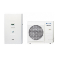
Provides overall physical dimensions, component identification, and pipe connection points.

Indoor Unit Installation Site

Location Selection and Plate Mounting

Guidelines for choosing an optimal location and securely mounting the unit's installation plate.

Wall Penetration for Piping

Instructions on drilling holes and installing sleeves for piping through walls.

Indoor Unit Mounting and Piping

Mounting and Refrigerant Pipe Installation

Steps for physically attaching the unit and connecting refrigerant pipes.

Water Piping Installation

Guidelines for connecting the water inlet, outlet, and drainage pipes.

Piping and Electrical Connections

Piping Preparation and Flaring

Instructions on properly cutting and flaring copper pipes for connections.

Electrical Wiring Procedures

Steps for wiring power supply and connecting cables to the indoor unit's terminal board.

Remote Controller Installation

Mounting and Removal Procedures

Instructions for installing the remote controller on the wall and its removal.

System Checks and Water Charging

Water Charging and System Checks

Procedures for filling the system with water and performing initial system checks.

Test Run and Maintenance

Test Run and Filter Maintenance

Performing a test run of the unit and maintaining the water filter set.

System Variations and Applications

System Configuration Overview

Overview of different system configurations and application examples for temperature control.

Optional Equipment Integration

Tank, Solar, and Buffer Tank Connections

Connecting DHW tanks, solar heaters, and buffer tanks to the system.

System Integration Details

Boiler, Buffer Tank, and External Wiring

Integrating boilers, buffer tanks, and wiring external devices.

PCB and Signal Connections

Main PCB and Signal Connections

Details on main PCB terminals, signal inputs/outputs, and optional PCB wiring.

External Device Specifications

Sensor and Device Details

Technical specifications for external sensors, pumps, and mixing valves.

Network Adaptor Installation

Network Adaptor Installation (Optional)

Instructions for installing the optional network adaptor for system connectivity.

Remote Controller Interface

Remote Controller Outline and Functions

Explanation of the remote controller's buttons, display, and operational functions.

Initial Power On and Setup

First Time Power On Initialization

Steps for initial system setup and language/time configuration upon first power activation.

Installer Setup Menu

Core Setup Options (PCB, Zone, Heater)

Configuring essential system settings like optional PCB, zones, and heater capacity.

System Setup Parameters

Tank, Solar, and Bivalent Settings

Configuring parameters for tank connections, solar integration, and bivalent operation.

Operation Mode Setup

Circulation, Heat-Cool, and Operation Modes

Setting circulation liquid, heat-cool switch, and configuring operation modes.

Operation Parameter Settings

Temperature and Delta T Settings

Setting target water temperatures and temperature differences for heating operations.

Tank Operation Settings

Tank Time and Sterilization Settings

Configuring tank operation times, heat-up duration, and sterilization cycles.

Service Setup and Diagnostics

Pump, Dry Concrete, and Service Contact

Settings for pump operation, dry concrete curing, and service contact information.

Service and Maintenance Functions

Service Menu Access and Functions

Accessing service menus, custom settings, and performing maintenance functions.

Related product manuals