1-10-2
11
(1) When linking the outdoor units in a network, disconnect the terminal extended from the short plug from
all outdoor units except any one of the outdoor units.
(When shipping: In shorted condition.)
For a system without link (no wiring connection between outdoor units), do not remove the short plug.
(2) Do not install the inter-unit control wiring in a way that forms a loop.
Outdoor unit Outdoor unit Outdoor unit
Indoor unit Indoor unit Indoor unit Indoor unit
Prohibited
Prohibited
Indoor unit
(3) Do not install inter-unit control wiring such as star branch wiring. Star branch wiring causes mis-address
setting.
(4)
Outdoor unit Indoor unitIndoor unit
Indoor unitIndoor unit
NO
Branch point
CAUTION
<Type E1>
If branching the inter-unit control wiring, the number of branch points should be 16 or fewer.
(Branches that are less than 1 m are not included in the total branch number.)
Indoor unit
Outdoor unit
Indoor unit Indoor unit Indoor unit
tinu roodtuOtinu roodtuO
Indoor unit Indoor unit Indoor unit Indoor unit
Indoor unit
Indoor unit
more than 1 m
less than 1 m
16 or fewer
Branch
Point
more than 1 m
(5)
(6)
Use shielded wires for inter-unit control wiring (c)
and ground the shield on both sides, otherwise
misoperation from noise may occur.
Connect wiring as shown in Section “ Wiring
System Diagrams” on page 1-10-2.
Shielded wire
(Functional earthing) (Functional earthing)
Loose wiring may cause the terminal to overheat
or result in unit malfunction. A fire hazard may also
occur. Therefore, ensure that all wiring is tightly
connected.
When connecting each power wire to the terminal, follow
the instructions on “How to connect wiring to the terminal”
on page 1-10-5 and fasten the wire securely with the
terminal screw.
WARNING
Use the standard power supply cables for
Europe (such as H05RN-F or H07RN-F which
conform to CENELEC (HAR) rating
specifications) or use the cables based on
IEC standard. (60245 IEC57, 60245 IEC66)
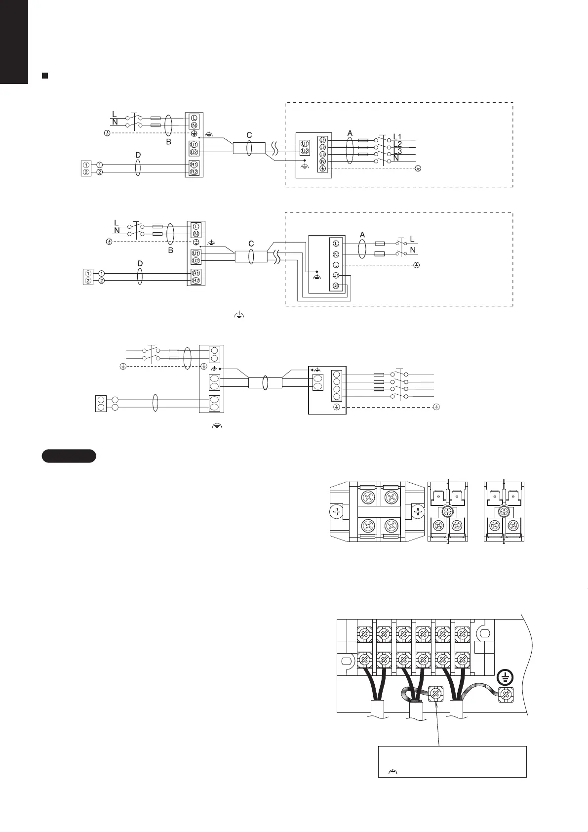
Wiring System Diagrams
<Type E1>
<Type E3>
Power supply
Indoor unit
Ground
Remote
controller
Remote
controller
Ground
(No.1)
Indoor unit
(No.1)
Power supply
230-240V ~50Hz
230-240V ~50Hz
* 3-phase model connections
* Single-phase model connections
Ground
Power supply
400 – 415 V 3 N~ 50Hz
Ground
Power supply
230 – 240 V ~50Hz
Outdoor unit (3-phase)
INV unit
Outdoor unit (single-phase)
INV unit
(
: Functional earthing)
NOTE
(1) See “Recommended Wire Length and Wire Diameter
for Power Supply System” on page 1-10-1 for the
explanation of “B”, “C” and “D” in the above diagram..
(2) The basic connection diagram of the indoor unit shows
the terminal boards, so the terminal boards in your
equipment may differ from the diagram.
(3) Refrigerant Circuit (R.C.) address should be set before
turning the power on.
(4) Regarding R.C. address setting, refer to the installation
instructions supplied with the outdoor unit. Auto address
setting can be executed by remote controller automatically.
Refer to the installation instructions supplied with the
remote controller (optional).
Type E3
Type E1
U2
U1
R2
R1
L
N
2
1
D
B
L
N
2
1
L1
L2
L3
N
C
L1
L2
L3
N
U2
U1
WHT
BLK
Ground
Ground
Indoor unit
( : Functional earthing )
Power supply
230-240V~ 50Hz
Remote
controller
Outdoor unit
Power supply
400-415V 3 N~ 50Hz
2P terminal board × 3
Power supply Remote
control
wiring
Inter-unit
control
wiring
L N U1 U2 R1 R2
R1
R2
U1
U2
NL
Use this screw when connecting the shleld
for the lnter-unit control wiring to ground.
( :Functional earthing)
Remote
controller
line
Unit
control
wiring
Power
suppy
Earth
6P terminal board
SM830277-00_大洋州向け R32シングル_TD&SM.indb 2 2019/02/27 11:50:38