10
Table 2 Ranges that Apply to Refrigerant Tubing Lengths and to Differences in Installation Heights
Unit: m
Item Mark Contents Length
Allowable tubing
length
L1 Max. tubing length
Actual length
200*
2
Equivalent length
210*
2
∆L (L2 – L4)
Difference between max. length and min. length from the 1st
distribution joint
50*
4
LM
Max. length of main tubing (maximum tubing size of discharge tube,
suction tube and liquid tube)
* Even after 1st distribution joint, LM is allowed if at maximum
tubing length.
-
*
3
1, 2~ 52
Max. length of each distribution tube
50*
5
L1 + 1 + 2~ 51 + A
+ B + LF + LG + LH
Total max. tubing length including length of each distribution tube (only
liquid tube)
500
A, B + LO, C + LO
Maximum tubing length from outdoor’s 1st distribution joint to each
outdoor unit
10
1-2, 2-2~ 52-2
Max. length between solenoid valve kit and indoor unit
30
Allowable elevation
difference
H1
When outdoor unit is installed higher than indoor unit
50
When outdoor unit is installed lower than indoor unit
40
H2 Max. difference between indoor units
15
H3 Max. difference between outdoor units
4
Allowable length of
joint tubing
L3
T-joint tubing (eld-supply); Max. tubing length between the rst T-joint
and solidly welded-shut end point
2
L*,
*
= Length H* = Height
1: The outdoor connection main tubing (LO portion) is determined by the total capacity of the outdoor units that are connected to the tube
ends.
2: If the longest tubing length (L1) exceeds 90 m (equivalent length), increase the sizes of the main tubes (LM) by 1 rank for the suction
tubes, discharge tubes and liquid tubes. Use a field supply reducer. Select the tube size from the table of main tubing sizes (Table 3) and
from the table of refrigerant tubing sizes (Table 8).
3: If the longest main tubing length (LM) exceeds 50 m, increase the main tubing size at the portion before 50 m by 1 rank for the suction
tubes and discharge tubes. Use a field supply reducer. Determine the length less than the limitation of allowable maximum tubing length.
For the portion that exceeds 50 m, set based on the main tubing size (LA) listed in Table 3.
4: If the tubing length marked “L” (L2 - L4) exceeds 40 m, increase the tubing size at the portion after the 1st distribution joint by 1 rank for
the liquid tube, suction tube and discharge tube.
Refer to the Technical Data for the details.
* Be sure to use special R410A distribution joints (CZ: optional parts) for outdoor unit connections and tubing branches.
LO
LA
LF
LM
LB
LC
L2
L3
L4
LG
LD
LH
H2
H3
H1
L1
2
1
6
5
A
B
C
50
51
52
3
2-1
2-2
3-1
3-2
4
4-1
4-2
4
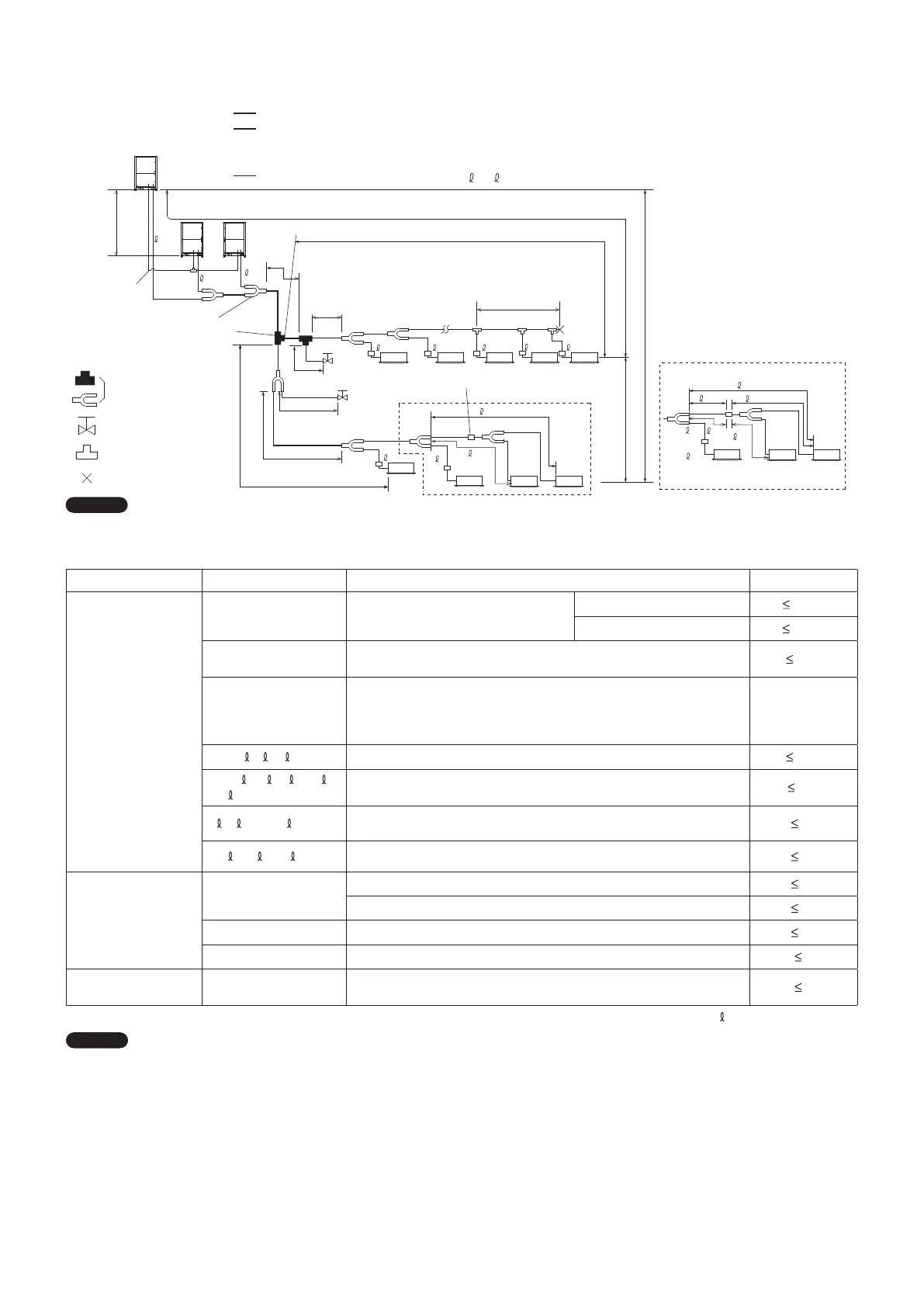
1-5. Tubing Length
Select the installation location so that the length and size of refrigerant tubing are within the allowable range shown in the gure below.
1.
Main tubing length (maximum tubing size of discharge tube, suction tube and liquid tube) LM = LA + LB …
2.
Main distribution tubes LC – LH are selected according to the capacity after the distribution joint.
3. The outdoor connection main tubing (LO portion) is determined by the total capacity of the outdoor units that are
connected to the tube ends.
4.
Sizes of indoor unit connection tubing
1 – 52 are determined by the connection tubing sizes on the indoor units.
R410A optional distribution joint
CZ-P680PH2 (for outdoor unit)
CZ-P1350PH2 (for outdoor unit)
CZ-P224BH2 (for indoor unit)
CZ-P680BH2 (for indoor unit)
CZ-P1350BH2 (for indoor unit)
Balance tube
(6.35mm)
Explanation of symbols
1st distribution joint for outdoor unit
1st distribution joint (for indoor unit)
Distribution joint
(CZ: optional parts)
For
extension
For
extension
Solenoid valve kit
Max. 40cm
Max. 40cm
Solidly welded shut
(pinch weld)
Ball valve (eld supply)
T-joint (eld supply)
00_341136_2WAY_Eng.indb 10 2022/9/19 9:27:13

 Loading...


