4 - 11
2WAY SYSTEM
Outdoor Unit Maintenance Remote Controller
4
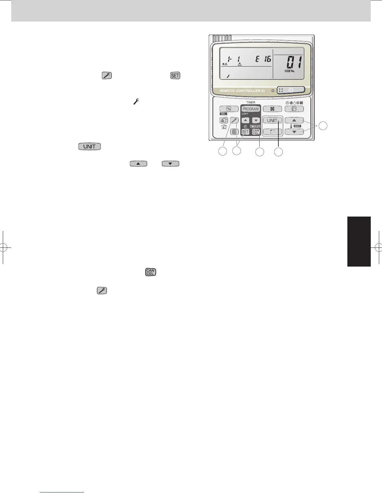
5. Outdoor Unit Alarm History Monitor
•
Displays outdoor unit alarms only.
•
Check the indoor unit alarm histories separately using the
indoor unit remote controllers or other control device.
<Operating procedure>
À
Press and hold the (CHECK) button and
button simultaneously for 4 seconds or longer to engage
outdoor unit alarm history mode.
During temperature monitoring,
illuminates.
The display and operations are the same as for the
alarm history monitor performed from the indoor unit
remote controller. However the “unit No.” display shows
the outdoor unit address.
Á
Press the button and select the outdoor unit for
which to monitor the alarm history.
Â
Press the temperature setting and
buttons and select the item code for the alarm history.
The select outdoor unit address, the item code, and the
alarm history (alarm data) are displayed.
The outdoor unit address is displayed as R.C. XX-YY.
System XX = Outdoor unit system address
R.C. XX = Outdoor unit system address
YY = Outdoor unit sub-bus address
Item codes 01-08 are displayed. 01 indicates the most
recent alarm.
The alarm history displays the alarm code. (If no alarm
are present, then -- -- is displayed.)
Ã
To clear the alarm history, press the button. (The
outdoor unit alarm history will be cleared.)
Ä
To exit, press the (CHECK) button. The display
returns to the normal display.
Display of unit No. 1 (main unit)
RemarksDescriptionDN
°C
°C
°C
°C
°C
°C
°C
°C
°C
°C
°C
°C
°C
°C
°C
°C
°C
°C
°C
°C
Indoor unit intake temp. (TA)
Indoor unit heat exchanger temp. E1 (E1)
—
Indoor unit heat exchanger temp. E3 (E3) Indoor unit
Discharge air temp. (BL)
Discharge air temp. setting
Indoor unit MOV pulse (MOV) STEP
Discharge temp. 1 (DISCH1)
Discharge temp. 2 (DISCH2)
High-pressure sensor temp.
Heat exchanger gas 1 (EXG1)
Heat exchanger liquid 1 (EXL1)
Heat exchanger gas 2 (EXG2)
Heat exchanger liquid 2 (EXL2)
Outdoor air temp. (TO)
—
AInverter primary current 1
A
A
CT2 Outdoor unit
STEPMOV pulse 1 (MOV1)
STEPMOV pulse 2 (MOV2)
Discharge temp. 3 (DISCH3)
CT3
Actual operating frequency
STEPMOV pulse 4 (MOV4)
—
—
Low-pressure sensor temp.
Suction temp. (SCT)
Detected oil temp. 1 (OIL1)
Detected oil temp. 2 (OIL2)
Detected oil temp. 3 (OIL3)
—
Temp. sensor at refrigerant gas outlet of dual-tube temp. (SCG)
Hz
NOTE
0A and subsequent items are outdoor unit data. 0A – 24 are for unit No. 1.
2A – 44 are for unit No. 2. 4A – 64 are for unit No. 3.
SM830228-013WAYECO-iSYSTEM.in1010 2013/07/
1
4 2
5
3
SM830204-05_2WAY SYS.indb 11 2015/01/23 11:57:00
 Loading...


