4 - 13
2WAY SYSTEM
Outdoor Unit Maintenance Remote Controller
4
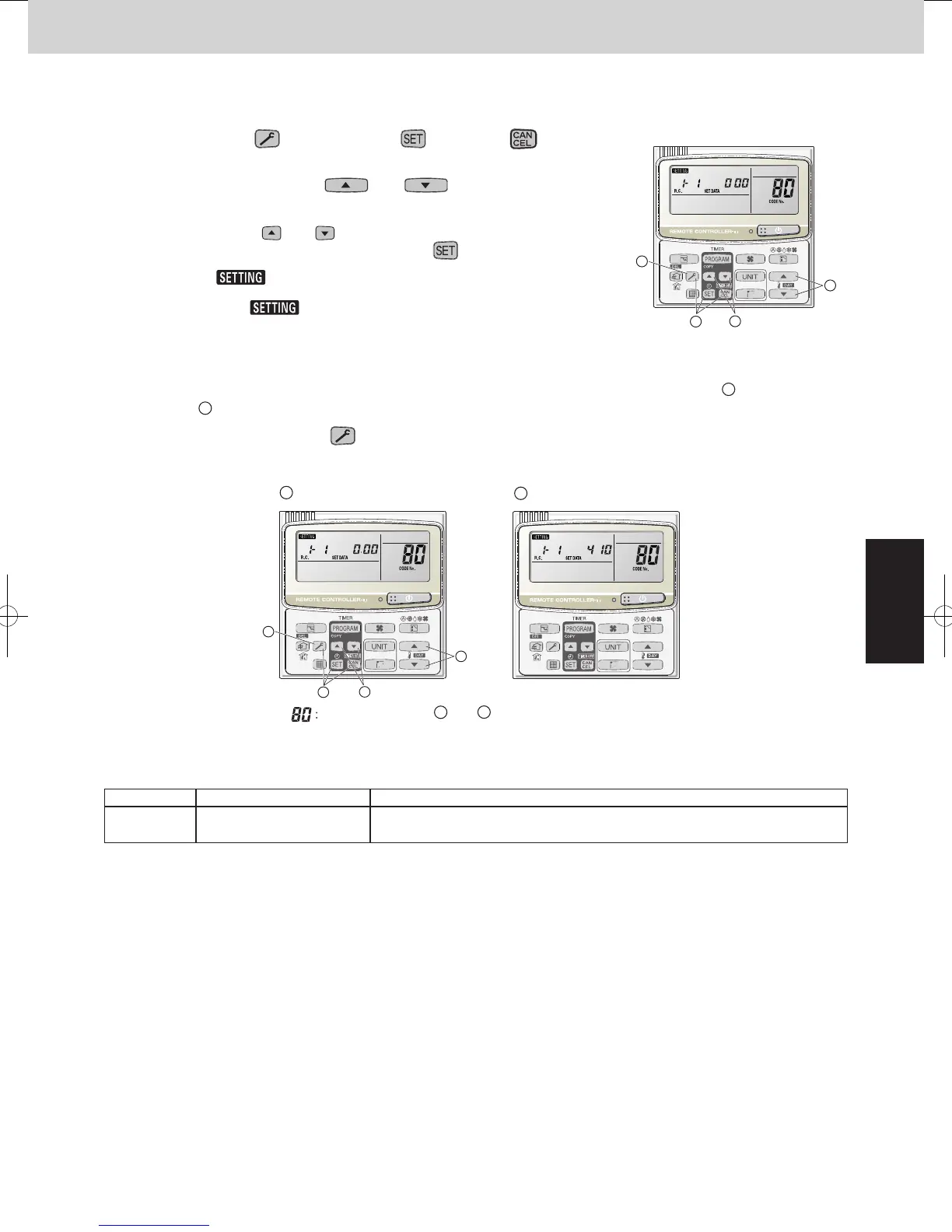
6. Mode Settings
n
Setting mode 2
<Operating procedure>
À
Press and hold the (CHECK) button, button, and button
simultaneously for 4 seconds or longer.
Á
Press the temperature setting and buttons to change the item
code. The item codes and setting data are shown in the table below.
Â
Press the timer time and buttons to change the setting data.
To confirm the changed setting data, press the button.
(At this time, “
” display stops blinking and remains lit.)
Ã
During this mode, “ ” is displayed, blinking. The display shows the set
outdoor unit address “System XX-YY” (System XX = System address, YY =
Address at outdoor unit sub-bus), item code number (DN value in the table
below), and the setting data (6 digits).
(The setting data is displayed in 6 digits. The display changes between the first 3 digits (Fig.
A
) and the last 3
digits (Fig.
B
). When the first 3 digits are displayed, the bottom point of the colon is lit.)
Ä
To exit setting mode, press the (CHECK) button. Returns to the normal display mode.
A
B
1
5
3
2
List of Item Codes
DN Parameter Description
81 Outdoor unit capacity
000 = Disabled, 224 = Type 8HP, 280 = Type 10HP, 355 = Type 12HP,
400 = Type 14HP, 450 = Type 16HP, 500 = Type 18HP, 560 = Type 20HP
1
2
5
3
Display of first 3 digits
<Refrigerant type>
A
and
B
are displayed alternately. (Example
shows 000 410 (R410A).)
Display of last 3 digits
Fig. 6
2WAY SYSTEM
Outdoor Unit Maintenance Remote Controller
6. Mode Settings
Setting mode 1
<Operating procedure>
Press and hold the 1
2
(CHECK) button and
(VENTILATION) button simultaneously for 4
seconds or longer.
Press the temperature setting
and
buttons to change the item code. The item codes
and setting data are shown in the table of “List of
Item Codes” on the next page.
Press the timer time
and buttons to
change the setting data.
To confirm the changed setting data, press the
button.
(At this time, “ ” display stops blinking
and remains lit.)
During this mode, “ ” is displayed,
blinking. The outdoor unit address display section
displays “ALL,” the item code and number (DN
value in the table), and the setting data (6 digits).
(The setting data is displayed in 6 digits. The
display changes between the first 3 digits (Fig.
A
)
and the last 3 digits (Fig.
B
B
B
A
A
).
When the first 3 digits are displayed, the bottom dot
of the colon is illuminated.)
To exit the setting mode, press the
(CHECK)
button.
1
2
3
5
5
3
1
2
and are displayed alternately.
(Example shows display of 000 001.)
Display of fi rst 3 digits
Display of last 3 digits
DescriptionParameterDN
Snowfall sensor usage
000 = Sensor input not present. Control is performed.
001 = Sensor input present. Control is performed.
002 = Sensor input not present. Control is not performed.
003 = Sensor input present. Control is not performed.
Outdoor unit fan Quiet
mode
000 = Disabled
002 = Quiet mode 2
001 = Quiet mode 1
003 = Quiet mode 3
004 = Quiet mode 4 ... 012 = Quiet mode 12
Energy saving mode
000 = None
001 = Discharge temp. control only (Mode 3)
002 = Demand only (Mode 2)
003 = Discharge temp. control + Demand (Mode 1)
Energy saving operation
plug
000 = Independent
001 = All indoor units linked
Demand 1 current
Demand 2 current
High static pressure mode
000 = Disabled 001 = High static pressure mode
* Charge when the external static pressure is increased to over 30 Pa.
3
4
5
130 = 130% ... -001 = no limit
000 = 0% 040 = 40% ... 070 = 70% ... 100 = 100% ...
000 = 0% 040 = 40% ... 070 = 70% ... 100 = 100% ...
130 = 130% ... -001 = no limit
SM830204-05_2WAY SYS.indb 13 2015/01/23 11:57:01
 Loading...


