27
3-4. Prepare the Tubing
● Material: Use seamless phosphorous deoxidized copper
tube for refrigeration. Wall thickness shall comply with the
applicable legislation. The minimal wall thickness must be
in accordance with the table below. For tubes of ø22.22 or
larger, use the material of temper 1/2H or H (Hard copper
tube). Do not bend the hard copper tube.
● Tubing size
Use the tubing size indicated in the table below.
● When cutting the tubing, use a tube cutter, and be sure to
remove any burrs.
The same applies to distribution tubing (optional).
● When bending the tubes, bend each tube using a radius
that is at least 4 times the outer diameter of the tube. When
bending, use sufficient care to avoid crushing or damaging
the tube.
● For flaring, use a flare tool, and be sure that flaring is
performed correctly.
CAUTION
Use sufficient caution during preparation of the tubing.
Seal the tube ends by means of caps or taping to prevent
dust, moisture, or other foreign substances from entering
the tubes.
Refrigerant tubing
Tubing size (mm)
Material Temper - O
(Soft copper tube)
Material Temper - 1/2 H, H
(Hard copper tube)
Outer dia. Thickness Outer dia. Thickness
ø6.35 t0.8 ø22.22 t1.0
ø9.52 t0.8 ø25.4 t1.0
ø12.7 t0.8 ø28.58 t1.0
ø15.88 t1.0 ø31.75 t1.1
ø19.05 t1.2 ø38.1 over t1.35
ø41.28 over t1.45
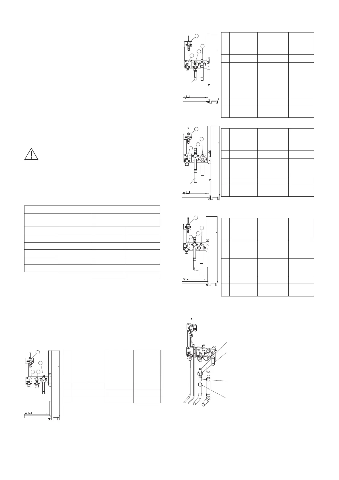
3-5. Connect the Tubing
● When operating the refrigerant tube installation in the
field, do not apply the flame of welding to the surrounding
sheet-metal parts. If necessary, use a wet rag to prevent
overheating of the heat exchanger.
● Use the supplied connector tubing.
1
2
3
4
10/12 HP
Supplied
tube
1
2
3
4
14 HP
16 HP
Supplied
tube
1
2
3
4
Supplied tube
1
2
3
4
Refrigerant
tubing
Connection
method
Use
Supplied
connector
tube?
1
Suction tube Brazing No
2
Discharge tube Flare No
3
Liquid tube Flare No
4
Balance tube Flare No
Refrigerant
tubing
Connection
method
Use
Supplied
connector
tube?
1
Suction tube Brazing No
2
Discharge
tube
Service valve
mounted on the
unit side: Flare
connection
Tubing side:
Brazing
Yes
ø15.88
Flare
↓
ø19.05
Brazing
3
Liquid tube Flare No
4
Balance
tube
Flare No
Refrigerant
tubing
Connection
method
Use
Supplied
connector
tube?
1
Suction tube Brazing No
2
Discharge
tube
Brazing
Yes
ø19.05
→ø22.22
3
Liquid tube Flare No
4
Balance
tube
Flare No
Refrigerant
tubing
Connection
method
Use
Supplied
connector
tube?
1
Suction tube Brazing
Yes
ø25.4
→ø28.58
2
Discharge
tube
Brazing
Yes
ø19.05
→ø22.22
3
Liquid tube Flare No
4
Balance
tube
Flare No
8 HP
Unit: mm
Unit: mm
Unit: mm
10/12 HP
Supplied
tube
1
2
3
4
14 HP
16 HP
Supplied
tube
In case of 10/12 HP
Flaring process to the tip of the
supplied tubes
Use the wide area of the outer tubing
surface of the supplied tubes.
•
Supplied tubing outer diameter ø19.05
•
Local tubing inner diameter ø19.05
Remove flare nuts attached to the service
valve and reuse them.
Note: Make sure the service valve is
completely closed.
If not, the gas leak will be occurred.
00_341136_2WAY_Eng.indb 27 2022/9/19 9:27:25
 Loading...


