1-831-82
1-9. Increasing the Fan Speed
Jumper cable
Jumper cable
Electrical component box
(At shipment) (Jumper cable installed)
2159_M_I
Fan motor socket
Fan
motor
900
Air Flow (CFM)
External Static Pressure
0
50
0
0.1
0.2
0.3
0.4
0.5
150
700500300
Limit line
L
100
1982_U_I
H
HH
(Pa)
(inAq)
Limit line
HT
Air Flow (CFM)
External Static Pressure
0
50
0
0.1
0.2
0.3
0.4
0.5
0.6
0.8
150
200
500 1000
Limit line
L
H
HH
HT
100
1983_U_I
(inAq)
(Pa)
Limit line
HT : Using the booster cable
H:At shipment
How to read the diagram
The vertical axis is the external static pressure (Pa) while the horizontal axis represents the AIR FLOW (CFM).
The characteristic curves for “HT”, “H”, “M” and “L” fan speed control are shown.
The nameplate values are shown based on the “H” air flow. For the Type 26, the air flow is 636 CFM, while the
external static pressure is 49 Pa at “H” position. If external static pressure is too great (due to long extension of
duct, for example), the air flow volume may drop too low at each air outlet.
This problem may be solved by increasing the fan speed as explained above.
If external static pressure is too great (due to long extension
of ducts, for example), the air flow volume may drop too low
at each air outlet. This problem may be solved by increasing
the fan speed using the following procedure:
(1) Remove 4 screws on the electrical component box and
remove the cover plate.
(2) Disconnect the fan motor sockets in the box.
(3) Ta ke out the jumper cable (sockets at both ends) clamped
in the box.
(4) Securely connect the jumper cable sockets
between the disconnected fan motor sockets in step 2.
(5) Place the cable neatly in the box and reinstall the cover
plate.
Indoor Fan Performance
Type 26 Type 36
Low Silhouette Ducted (Type F1)
NOTE
1-10. External Static Pressure Setting
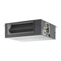
Concealed Duct (Type F2)
For concealed duct type indoor units, the ventilating resistance so-called “external static pressure” becomes greatly
different depending on the connected duct length, shape, number of air outlet ports and types of filters.
When installing this unit, be sure to carry out the external static pressure setting in order to operate in the rated airflow
volume. Choose one of the following methods from “a”, “b”, “c” or “d” as shown in the flow chart (within the dotted lines)
and then make the setting accordingly.
a. No setting modification .............................................................................: Use-as-is at shipment (there are cases in which the
setting may differ from the shipment setting when
reset after once setting the external static pressure.)
b. Manual setting (set with the PC board) ....................................................: For high static pressure. Switching method with the
short-circuit connector.
c. Manual setting (set with the wired remote controller) ...............................: Low static pressure ~ high static pressure
d. Auto airflow volume setting (set on the wired remote controller) .............: Air outlet volume is automatically adjusted to the rated
airflow volume with the auto airflow control drive.
Flow of External Static Pressure
Finish the ducting and electrical wiring and prepare it for use. (Note (1))
External static pressure should be set during initial operations after installation (before
the cooling and heating test run).
When operating with group control (connecting multiple indoor units with one wired
remote controller), make the concealed duct type to the main unit.
Start external static pressure setting
a. No setting modification
b. Manual setting
(set with the PC board)
TP3 or TP1 short-circuit
Refer to section “1-10-1.
How to Set on PC Board”.
c. Manual setting
Item code “b0” : 0~15 setting
(*Note (3)) (* Note (4))
Refer to section 1-10-2 or 1-10-3.
d. Auto airflow volume setting
(* Note (4)) Item code “b0” :
-2 setting
Refer to section 1-10-2 or 1-10-3.
Operation checks for external static pressure settings (*Note (2))
Refer to section 1-10-2 or 1-10-3.
Check if the setting is within the range of use on the PQ diagram.
If out of range, adjust until it becomes within the range of use.
This can be omitted if deemed unnecessary in the event of the same installation/set-up being available.
Auto airflow volume control
operations (*Note (5))
Refer to section 1-10-2 or 1-10-3.
Test operation display will disappear. (*Note (6))
External static pressure setting completed
Timer remote controller available
Lines
15
and
14
settings (high static pressure) on
the PQ diagram required
Set the rated airflow
volume with the exception of lines
15
,
14
and,
8
Line
8
(set at
shipment) on the PQ diagram
designed and installed
No
No
No
No
Ye s
Ye s
Ye sYes
1
SM830203-04.indb 82 15/10/16 10:44:45

 Loading...
