5-5. Finishing the Installation
from entering.
Apply putty here
Tubing
6. BEFORE SWITCHING ON
● Check if the filter is installed properly.
●
Check if the horizontal airflow direction louver works properly.
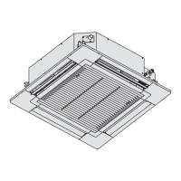
Type 45, 56, 73, 106
Front panel
Vertical airflow direction louver
s$ONOTADJUSTBYHAND
Horizontal airflow direction louver
s-ANUALLYOPERATEDADJUSTABLELOUVERS
Air filters
Indicator
Receiver
7. HOW TO INSTALL TIMER REMOTE
CONTROLLER OR HIGH-SPEC WIRED
REMOTE CONTROLLER (OPTIONAL
PART)
N OT E
Refer to the Operating Instructions attached to the optional
Timer Remote Controller or optional High-Spec Wired Remote
Controller.
8. PRECAUTIONS ON TEST RUN
● Request that the customer be present when the test run is
performed. At this time, explain the operation manual and
have the customer perform the actual steps.
● Check that the 220 – 240 V AC power is not connected to
the inter-unit control wiring connector terminal.
* If 220 – 240 V AC is accidentally applied, the indoor unit
control PCB fuse will blow in order to protect the PCB.
In this case, make the wiring correctly. Then reconnect the
connector to pins 2 and 3 from pins 1 and 2 on the 3P DIP
pin (EMG).
If the operation is not activated even if the short circuit pin
is reconnected, cut the jumper on the indoor unit PCB.
(Be sure to turn the power OFF before performing this
work.)
3
1
123
3P DIP pin (EMG)
Short circuit pin
EMG (CN044)
Jumper
(JP040)
00_292008_ALL.indb 202017/8/31 13:31:19
 Loading...