EasyManua.ls Logo

Panasonic SA-AK250 Service Manual

Panasonic SA-AK250
102 pages
To Next Page IconTo Next Page
Page #1 background imageLoading...
Page #1 background image
RMS output power
THD 10%, both channels driven
1 kHz 115 W per channel (3 )
Total output power 230 W
PMPO 2500 W
n FM/AM TUNER, TERMINALS SECTION
Preset station FM 20 stations
AM 15 stations
Frequency Modulation (FM)
Frequency range 87.9 to 107.9 MHz (200 kHz
steps)
87.5 to 108.0 MHz (100 kHz
steps)
Sensitivity 4.0 µV (IHF)
S/N 26 dB 2.2 µV
A
ntenna terminal(s) 75 (unbalanced)
A
mplitude Modulation (AM)
Frequency range 520 to 1710 kHz (10 kHz step)
Sensitivity
S/N 20 dB (at 1000 kHz) 560 µV/m
A
udio performance (Amplifier)
Input Sensitivity/ Input Impedance
A
ux 250 mV, 14.7 k
Music Port input jack
© 2007 Matsushita Electric Industrial Co. Ltd.. All
rights reserved. Unauthorized copying and
distribution is a violation of law.
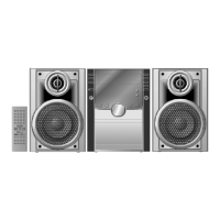
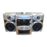
SA-AK250PL
Colour
(S)... Silver Type
Terminal Stereo, 3.5 mm jack
Sensitivity 100 mV, 4.7 k
Phone jack
Terminal Stereo, 3.5 mm jack
n CASSETTE DECK SECTION
Track system 4 track, 2 channel
Heads
Record/playback Solid permalloy head
Erasure Double gap ferrite head
Motor DC servo motor
Recording system AC bias 100 kHz
Erasing system AC erase 100 kHz
Tape speed 4.8 cm/s
Overall frequency response (+3, -6 dB) at DECK OUT
NORMAL 35 Hz to 14 kHz
S/N ratio 50 dB (A weighted)
Wow and flutter 0.18 % (WRMS)
Fast forward and rewind time Approx. 120 seconds with
C-60 cassette tape
n DISC SECTION
Disc played [8 cm or 12 cm]
(1) CD-Audio (CD-DA)
(2) CD-R/RW (CD-DA, MP3* formatted disc)
CD Stereo System
Notes: This model’s CD mechanism changer unit is CRS1. Please refer to the original Service Manual
(Order No. MD0509368C0) for this mechanism.
Specifications
ORDER NO. MD0704054CE

Table of Contents

Question and Answer IconNeed help?

Do you have a question about the Panasonic SA-AK250 and is the answer not in the manual?

Panasonic SA-AK250 Specifications

General IconGeneral
Speakers2
CD PlayerYes
Number of Discs5
Playable MediaCD, CD-R/RW
Radio TunerYes
TunerFM/AM
BluetoothNo
USB PlaybackNo
InputsAUX
OutputsHeadphone
Speaker Type2-Way
Tape DeckYes

Summary

Specifications

RMS Output Power

Technical specifications for audio output.

FM/AM Tuner and Terminals

Details on radio tuner and connection terminals.

Cassette Deck Section

Technical specifications for the cassette tape mechanism.

Disc Section

Details on CD playback capabilities.

Safety Precautions

General Guidelines

General advice for safe operation and maintenance.

Leakage Current Checks

Procedures for electrical safety checks.

Before Repair and Adjustment

Precautions before starting repairs.

Protection Circuitry

Information on the unit's protection circuits.

Safety Part Information

Details on critical safety components.

Electro Static Discharge (ESD) Prevention

Handling ES Devices

Techniques to prevent damage to sensitive electronic components.

Laser Diode Precautions

Traverse Unit Handling

Guidelines for safely handling the optical pickup traverse unit.

Laser Safety

Warnings and precautions regarding laser radiation.

Lead-Free Solder (PbF)

Repair Cautions

Guidelines for working with lead-free solder.

Recommended Solder

Part numbers for lead-free solder types.

Accessories

Included Accessories

List of items included with the main unit.

Operating Procedures

Main Unit Controls

Explanation of buttons and functions on the main unit.

Remote Control Operations

Guide to using the remote control unit.

New Features

Using the Music Port

Instructions for connecting and using external audio devices.

Self-Diagnosis and Special Modes

Service Mode Summary

Overview of available diagnostic and test modes.

Special Mode Table

Details on specific service modes and their operations.

Error Code Display

Deck Mechanism Error Codes

Table listing error codes for the deck mechanism.

CD Changer Error Codes

Table listing error codes for the CD changer.

Power Supply Error Codes

Table listing error codes for the power supply.

CRS1 Error Code Display

Procedure to display and clear CRS1 error codes.

Assembling and Disassembling

General Cautions & Flow Chart

Safety notes and visual guide for disassembly.

Top Cabinet & Rear Panel Disassembly

Instructions for removing the top cabinet and rear panel.

Main PCB & Power Supply Disassembly

Instructions for removing the main and power supply PCBs.

Mechanism Units Disassembly

Steps for disassembling CD changer, deck, and traverse units.

Deck Mechanism Components & Tape Jam

Disassembly of deck mechanism parts and tape jam rectification.

Component Replacement Procedures

Procedures for replacing pinch rollers, motors, and belts.

Service Fixture and Tools

Required Service Tools

List of specialized tools and fixtures for servicing.

Service Positions

Checking Main P.C.B.

Procedure for checking and repairing the main PCB.

PCB Checking and Repairing

Transformer P.C.B.

Procedure for checking and repairing the transformer PCB.

Panel, Deck & Deck Mechanism P.C.B.

Procedure for checking and repairing multiple PCBs.

Power P.C.B.

Procedure for checking and repairing the power PCB.

Deck Mechanism Operation Check

With Cassette Tape

Procedure for checking deck operation with a cassette.

Without Cassette Tape

Procedure for checking deck operation without a cassette.

Measurement and Adjustments

Cassette Deck Section Requirements

Tools and materials needed for cassette deck measurements.

Cassette Deck Settings

Unit settings required for measurement procedures.

Cassette Deck Preparations

Steps to prepare for cassette deck measurements.

Tape Speed Adjustment

Procedure for adjusting the tape playback speed.

Bias Voltage Check

Procedure for checking bias voltage in the cassette deck.

Bias Frequency Check

Procedure for checking bias frequency in the cassette deck.

Voltage and Waveform Chart

CD Servo P.C.B. Chart

Voltage and waveform data for the CD servo PCB.

Deck P.C.B. & Deck Mechanism P.C.B. Chart

Voltage and waveform data for deck PCBs.

PCB Voltage and Waveform Data

Main P.C.B. Chart

Voltage and waveform data for the main PCB.

Panel & Transformer P.C.B. Chart

Voltage and waveform data for panel and transformer PCBs.

Power P.C.B. Chart

Voltage and waveform data for the power PCB.

Waveform Chart

Visual examples of various waveforms.

Wiring Diagrams

Wiring Connection Diagram

Diagram showing all electrical connections between components.

Block Diagrams

CD Servo Block Diagram

Functional block diagram of the CD servo system.

Deck/Deck Mechanism Block Diagram

Functional block diagram of the deck mechanism.

Main Block Diagram

Overall functional block diagram of the unit.

Panel Block Diagram

Functional block diagram of the panel section.

Power Block Diagram

Functional block diagram of the power supply section.

Transformer Block Diagram

Functional block diagram of the transformer section.

Schematic Diagram Notes

Notes on Symbols and Lines

Explanation of symbols and line types used in schematics.

Schematic Diagrams

CD Servo Circuit

Schematic diagram for the CD servo circuit.

Main Circuit

Schematic diagram for the main unit circuits.

Panel Circuit

Schematic diagram for the panel circuit.

Sub Panel & Deck Mechanism Circuit

Schematic diagrams for sub-panel and deck mechanism.

Power Circuit

Schematic diagram for the power supply circuit.

Deck Circuit

Schematic diagram for the deck section.

Transformer Circuit

Schematic diagram for the transformer circuit.

Printed Circuit Board Diagrams

CD Servo, Deck, Deck Mechanism PCBs

Layout diagrams for CD servo, deck, and deck mechanism PCBs.

Main PCB Layout

Layout diagram for the main printed circuit board.

Panel PCB Layout

Layout diagram for the panel printed circuit board.

Sub Panel PCB Layout

Layout diagram for the sub panel printed circuit board.

Power PCB Layout

Layout diagram for the power supply printed circuit board.

Transformer PCB Layout

Layout diagram for the transformer printed circuit board.

Component Identification

ICs, Transistors, and Diodes

Illustrations and part numbers for electronic components.

IC Terminal Functions

IC7001 Functions

Pin functions for the CD servo processor IC.

IC7002 Functions

Pin functions for the 4-channel drive IC.

IC2801 Functions

Pin functions for the system microprocessor IC.

Exploded Views

Cabinet Parts Location

Diagram showing the location of cabinet parts.

Deck Mechanism Parts Location

Diagram showing the location of deck mechanism parts.

Packaging Details

Illustration of the product's packaging.

Replacement Parts List

General Parts Information

Important notes on part replacement and component types.

Cabinet and Mechanism Parts

Replacement parts for the unit's exterior and internal mechanisms.

Electronic Components

Lists of ICs, transistors, diodes, resistors, capacitors, etc.

Connectors, Coils, and Fuses

Replacement parts for connections, inductors, and protection.

Miscellaneous Parts

Lists for oscillators, displays, holders, jacks, wires, and jumpers.

Related product manuals