Do you have a question about the Panasonic SA-AK230GCP and is the answer not in the manual?
Details the RMS output power and THD specifications for the amplifier.
Covers preset station capacity and frequency ranges for FM and AM tuning.
Lists specifications for tape system, heads, motor, recording, and tape speed.
Outlines supported disc types, bit rates, sampling frequencies, and decoding.
Instructions for initial setup and voltage selection before operating the unit.
Guidelines for disconnecting power and discharging capacitors before servicing.
Explains the unit's protection circuit and how to reset it if triggered.
Techniques to prevent damage to sensitive electronic components from static electricity.
Information on identifying and safely working with lead-free solder used in the device.
Specific handling instructions for the traverse deck to prevent laser diode damage from static.
Methods for grounding the body and workspace to prevent electrostatic discharge.
Warnings and guidelines for safe operation and handling related to the laser diode.
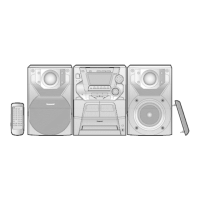
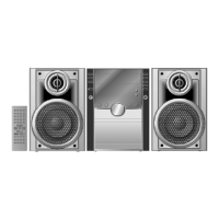
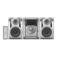
Lists and illustrates the accessories provided with the CD Stereo System.
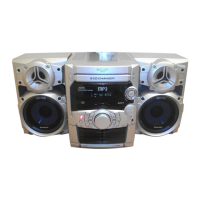
Overview of buttons and functions on the main unit's front panel.
Details the specific functions assigned to buttons on the remote control.
Explains compatibility with Audio CD and CD-R/RW, including MP3 format.
Details file format requirements, naming conventions, and limitations for MP3 playback.
Provides a step-by-step visual guide for disassembling the main component assembly.
Instructions on preparing and using a specific gear as a service tool for manual operations.
Details the procedure for removing the top cabinet of the unit.
Step-by-step instructions for removing the CD lid after the top cabinet is detached.
Describes how to manually open the disc tray using service tools if automatic function fails.
Steps for removing the rear panel of the main unit.
Instructions for detaching the entire CD mechanism unit from the chassis.
Steps to remove the main printed circuit board assembly.
Procedure for removing the power printed circuit board.
Steps for replacing the power amplifier IC or voltage regulator components.
Instructions for removing the transformer printed circuit board.
Procedure for removing the front panel assembly of the unit.
Steps to remove the cassette deck mechanism unit.
General procedures for replacing main components within the CD mechanism.
Detailed steps for replacing the traverse deck assembly within the CD mechanism.
Specific steps for lifting, removing, and detaching the traverse deck assembly.
Steps for installing the CD servo P.C.B. after component replacement.
Procedures for correctly installing the traverse deck assembly.
Detailed steps for removing and replacing the disc tray assembly.
Steps to manually remove the disc tray after accessing the mechanism.
Procedures for reinstalling the disc tray after replacement.
Steps for disassembling and reassembling the drive unit of the mechanism.
Instructions for releasing and removing the tray lock and rear lock mechanisms.
Steps for lifting and removing the spindle base unit from the mechanism.
Procedures for disassembling and reassembling the spindle base unit.
Steps to rotate and draw out the disc lever during mechanism disassembly.
Instructions for releasing claws and drawing out the relay gear B.
Steps for releasing claws and removing the relay gear A.
Procedure for removing the spindle shaft and releasing the spindle stopper.
Steps to align and latch the loading stopper assembly into place.
Procedures for reinstalling traverse cam gear, drive gear, and traverse relay gear.
Steps to install slide plates 1 and 2 into the mechanism base.
Procedure for installing the spindle base unit, starting with slide plate 1.
Steps for installing the tray lock, UP/DOWN gear, change gear, and pulley gear.
Detailed steps for removing and installing the motor assembly on the traverse ass'y.
Instructions for releasing claws to remove pinch rollers and head connector.
Procedure for replacing deck motors, capstan belts, and winding belts.
Steps for installing winding belts onto pulleys and flywheels.
Procedures for installing capstan belts A and B onto the motor assembly.
Steps for putting capstan belt B onto the motor assembly.
Steps for putting capstan belt A onto the motor assembly pulley.
Steps to lift the lever and push the cassette lid assembly to remove it.
Procedure to remove a jammed cassette tape by rotating the flywheel and opening the lid.
Steps required to access and check the main printed circuit board.
Steps for accessing and performing checks on the transformer printed circuit board.
Procedures for checking panel, deck, and deck mechanism PCBs using extension cables.
Steps for accessing and checking the power printed circuit board, including insulation.
Explanation of the unit's self-diagnostic display function for error codes.
Step-by-step guide on how to activate the self-diagnostic mode.
Procedure for testing cassette mechanism functions and interpreting error codes.
Steps for testing CD mechanism functions and identifying error codes.
Instructions on how to reset and clear all recorded error codes.
Method to safely exit the self-diagnostic mode.
Provides a detailed explanation of the error codes encountered during diagnostics.
Lists error codes and their descriptions related to the deck mechanism.
Lists error codes and their descriptions for CD/Changer block abnormalities.
Details error codes related to power supply abnormalities, like F61.
Explains error codes for mechanism problems and provides a mechanism error code table.
Instructions on how to activate the CD test mode for diagnostics.
How to interpret the results of automatic CD adjustments shown on the FL display.
Details the CD aging test mode for reliability determination and how to enter it.
How to display software version and ROM checksum for microcomputer diagnostics.
Pre-measurement checks for the cassette deck, like head cleanliness and temperature.
Lists the instruments required for measurements, like EVM and frequency counter.
Specifies the type of test tape used for gain adjustment and speed tests.
Procedure for adjusting tape speed for DECK 2 and verifying DECK 1 output frequency.
Steps to check bias and erase voltage levels using a blank tape in REC mode.
Procedure for adjusting bias frequency output within standard values using a blank tape.
Steps for aligning the AM Intermediate Frequency circuit using test equipment.
Steps for adjusting AM Radio Frequency circuits for optimal reception.
Identifies specific alignment points for the cassette deck section.
Identifies specific alignment points for the tuner section.
Block diagram showing the optical pickup and semiconductor laser components.
Block diagram illustrating the functions of the IC7003 for drive control.
Block diagram detailing the functions of the IC7002 servo processor and digital signal processor.
Schematic details for the FM/AM IF amplifier, detector, and multiplex decoder (IC2601).
Schematic details for the PLL frequency synthesizer (IC2602).
Schematic of the microprocessor and its connections to various peripherals and displays.
Schematic of the FL display driver and remote sensor interface.
Schematic for the PB EQ/REC AMP/ALC/TPS AMP circuit.
Schematic connections for the record/playback and erase heads.
Schematic of the audio sound processor and its related input/output connections.
Schematic of muting circuits and various control switches.
Schematic of the power HIC, voltage regulators, and power switching circuits.
Explanation of the different types of signal lines used in the wiring diagrams.
Table detailing voltage measurements for IC2801 and IC2802 on the main PCB.
Table detailing voltage measurements for Q2936, Q5950, Q5951, Q5952, Q5953, Q5954 on PCBs.
Explains that diagrams may be modified and provides a switch function list.
Highlights safety precautions for components marked with Delta and general repair safety.
Schematic details of the optical pickup circuit, including laser diode and photo detector.
Schematic diagram of the CD servo control circuit, featuring IC7003.
Schematic diagram of the CD servo circuit, focusing on IC7002 functions.
Schematic details for the FM/AM IF amplifier, detector, and multiplex decoder (IC2601).
Schematic details for the PLL frequency synthesizer (IC2602).
Schematic detailing the main circuit, including control switches and motor drivers.
Schematic of the main circuit, showing microprocessor interface and audio control.
Schematic of the main circuit, illustrating microprocessor connections and output interfaces.
Schematic of the main circuit, showing connections to tuner, power, and audio circuits.
Schematic of the panel circuit, including switches, volume control, and LED drivers.
Schematic of the panel circuit, focusing on the FL display driver and its connections.
Schematic of the transformer circuit, including AC input and voltage selection.
Schematic of the CD detection circuit.
Schematic of the spindle position detection circuit.
Schematic of the CD loading mechanism control circuit.
Schematic of the power supply circuit, including regulators and protection.
Schematic of the cassette deck circuit, including head amplifiers and control ICs.
Schematic of the deck mechanism circuit, showing photo interrupters and motor controls.
Physical layout diagram of the CD Servo P.C.B. (REPX0443A).
Physical layout diagram of the Main P.C.B. (REPX0442W).
Physical layout diagram of the Main P.C.B., showing component placement.
Physical layout diagram of the Panel P.C.B. (REPX0441C).
Physical layout diagram of the Panel P.C.B., showing switches and connectors.
Physical layout diagram of the Transformer P.C.B. (REPX0468D).
Physical layout diagram of the CD Detect P.C.B. (REP2578A-N).
Physical layout diagram of the Spindle Position P.C.B. (REP2578A-N).
Physical layout diagram of the CD Loading P.C.B. (REP2578A-N).
Physical layout diagram of the Tuner Pack P.C.B. (REP1999B).
Physical layout diagram of the Power P.C.B. (REPX0469K).
Physical layout diagram of the Power P.C.B., showing component placement.
Physical layout diagram of the Deck P.C.B. (REPX0331D).
Physical layout diagram of the Deck Mechanism P.C.B. (REPX0321A).
Visual representation of how different PCBs and components are interconnected.
Visual identification of common ICs, transistors, and diodes used in the unit.
Detailed pin descriptions and functions for the IC7002 Servo Processor.
Detailed pin descriptions and functions for the IC7003 Drive Controller.
Detailed pin descriptions and functions for the IC2801 Microprocessor.
A flowchart to diagnose and resolve common issues with the CD playback mechanism.
Important notes regarding safety, component markings, and language references for the parts list.
Exploded view showing the location of various parts within the deck mechanism.
Further exploded views detailing component placement in the deck mechanism.
Comprehensive list of part numbers and descriptions for cassette deck components.
Exploded view showing the location of parts within the CD loading mechanism.
Further exploded views detailing component placement in the CD loading mechanism.
Comprehensive list of part numbers and descriptions for CD loading mechanism components.
Exploded views showing the location of cabinet components and chassis parts.
Further views detailing the placement of cabinet components, PCBs, and connectors.
List of part numbers for cabinet, chassis, and related hardware.
List of part numbers for all printed circuit boards.
List of integrated circuits with their part numbers and descriptions.
List of transistors with their part numbers and descriptions.
List of diodes with their part numbers and descriptions.
Continuation of the diode list with part numbers and descriptions.
List of variable resistors used in the unit.
List of various switches and their part numbers.
List of connectors with their part numbers and descriptions.
List of ceramic filters used in the circuit.
List of coils and transformers with part numbers.
List of combined components like resistors, sensors, and oscillators.
List of oscillators and their part numbers.
List of fuses, their part numbers, and ratings.
List of fuse holders and their part numbers.
List of various holders and their part numbers.
List of jacks and connectors with their part numbers.
List of earth terminals and their part numbers.
List of wires and cables with their part numbers.
List of chip resistors, their part numbers, and values.
Continuation of the chip resistor list with part numbers and values.
Further continuation of the chip resistor list with part numbers and values.
Final continuation of the chip resistor list with part numbers and values.
List of capacitors with their part numbers, values, and voltage ratings.
Continuation of the capacitor list with part numbers and values.
Further continuation of the capacitor list with part numbers and values.
List of packing materials and accessories provided with the unit.
Diagram illustrating how the unit and its accessories are packaged for shipping.
| Brand | Panasonic |
|---|---|
| Model | SA-AK230GCP |
| Category | Stereo System |
| Language | English |