Do you have a question about the Panasonic SA-AK220E and is the answer not in the manual?
Specifications for the amplifier section.
Performance metrics for the cassette deck.
Technical data for the CD player.
Crucial safety information about the AC mains lead.
Important steps before starting repair work.
Measures to prevent ESD damage to components.
Safety warnings and handling advice for the laser diode.
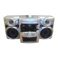
Guide to operating the unit using its front panel controls.
Overview of the disassembly process.
Steps to remove the top cabinet and rear panel.
Steps to remove the CD mechanism unit.
Instructions for disassembling main, transformer, and power PCBs.
Steps to remove the deck mechanism and its PCB.
Guides for replacing key CD mechanism parts.
Steps to replace the pinch roller and head block.
Solutions for common tape playback issues.
Specific steps for inspecting key PCBs.
Table of error codes for the deck mechanism.
Table of error codes for the CD/changer.
Steps to activate the diagnostic mode.
Test procedure for the cassette mechanism.
Specific troubleshooting for power amplifier failures (F61).
Procedure to set up the CD unit for testing.
Measurements and adjustments for the cassette deck.
Measurements and adjustments for the tuner section.
High-level block diagram of the system.
Detailed schematic of the CD servo system.
Schematic for deck audio and control circuits.
Component layout for the CD servo PCB.
Component layout for the main PCB.
Component layout for the panel PCB.
Component layout for the tact switch PCB.
Component layout for the transformer PCB.
Component layout for the CD loading PCB.
Component layout for the power PCB.
Component layout for the deck PCB.
Component layout for the deck mechanism PCB.
Diagram showing interconnections between major units.
Pinout and functions for IC701 (Servo Amplifier).
Pinout and functions for IC305 (Microprocessor).
Step-by-step guide for diagnosing problems.
Critical safety information for replacing components.
Comprehensive list of electrical components.
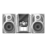
| Number of speakers | 2 |
|---|---|
| Total Harmonic Distortion | 10 % |
| CD Player | Yes |
| Disc capacity | 1 |
| Radio | Yes |
| USB Port | No |
| Bluetooth | No |
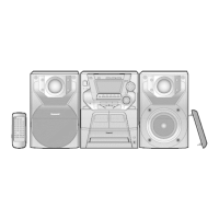
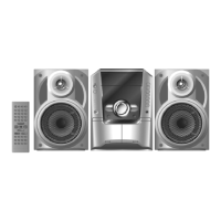
| Remote Control | Yes |
| Cassette deck | Yes |
| Type | Mini System |
| Speaker Configuration | 2.0 |
| Impedance | 6 Ohm |
| Playback media | CD-R, CD-RW |
| Tuner bands | FM |