Mass 7.3 kg
n SYSTEM
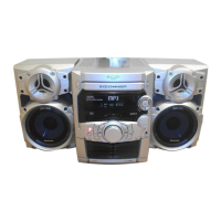
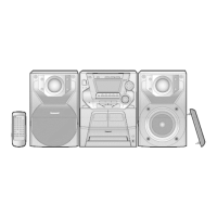
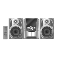
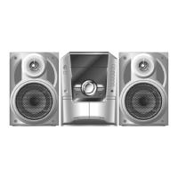
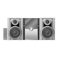
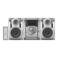
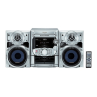
SC-AK220 (E) Music center: SA-AK220 (E)
Speaker: SB-AK220 (GC)
SC-AK220 (EB) Music center: SA-AK220 (EB)
Speaker: SB-AK220 (GC)
1 Caution for AC Mains Lead
4
2 Before Repair and Adjustment
5
3 Protection Circuitry
5
4 Prevention of Electro Static Discharge (ESD) to
Electrostatically Sensitive (ES) Devices
5
5 Handling the Lead-free Solder
6
5.1. About lead free solder (PbF)
6
6 Handling Precautions For Traverse Deck
7
7 Precaution of Laser Diode
8
8 Accessories
9
9 Operation Procedures
10
10 Disassembly and Assembly of Main Component
11
10.1. Disassembly flow chart
11
10.2. Disassembly of Top Cabinet and Rear Panel
12
10.3. Disassembly of CD Mechanism Unit
14
10.4. Disassembly Main P.C.B., Transformer P.C.B. & Power
P.C.B.
15
10.5. Disassembly of Panel P.C.B. & Tact Switch P.C.B.
16
10.6. Disassembly of Deck Mechanism Unit & Deck P.C.B.
17
10.7. CD Mechanism Main Component Replacement
Procedures
18
10.8. Replacement for the pinch roller ass 馳 and head block
31
10.9. Replacement for the Deck motor ass 馳, capstan belt A,
capstan belt B and winding belt
31
10.10. Replaceme nt for the cassette lid ass 馳
34
10.11. Counter-me asure for tape trouble
34
11 Service Position
35
11.1. Checking Procedure
35
11.2. Checking the Main P.C.B., Power P.C.B. and Transformer
P.C.B.
35
11.3. Checking the Panel, Tact Switch, Deck & Deck
Mechanism P.C.B.
36
12 Description of Error Code
37
12.1. Abnormality detection for Deck Mechanism block
37
12.2. Abnormality detection for CD/Changer block
37
12.3. Power Supply related error detection
37
13 Self-Diagnostic Function
38
Notes:
1. Specifications are subject to change without notice. Mass and
dimensions are approximate.
2. Total harmonic distortion is measured by the digital spectrum
analyzer.
3. The labels “HIGH” and “LOW” on the rear of the speakers refer
to High frequency and Low frequency.
13.1. Self-diagnostic display
38
13.2. How to enter the Self-Diagnostic Function
38
13.3. Cassette Mechanism Test (For error code H01, H02, H03,
F01, F02)
38
13.4. CD Mechanism Test (F15, F26, F16, F17, F27, F28, F29,
H15)
39
13.5. To clear all Error code
39
13.6. How to get out from Self-Diagnostic function
39
13.7. Power Amplifier Failure (F61)
39
14 CD Test Mode Function
40
14.1. How to set CD test mode
40
14.2. CD Automatically Adjustment result indication
40
15 Measurements and Adjustments
41
15.1. Cassette Deck Section
41
15.2. Tuner Section
41
15.3. Alignment Points
42
16 Block Diagram
43
17 Schematic Diagram
50
17.1. (A) CD Servo Circuit
51
17.2. (B) Tuner/Main Circuit
53
17.3. (B) Main Circuit
54
17.4. (C) Panel Circuit & (D) Tact Switch Circuit
59
17.5. (E) Transformer Circuit, (F) CD Detect Circuit, (G) Spindle
Position Circuit & (H) CD Loading Circuit
61
17.6. (I) Power Circuit
62
17.7. (J) Deck Circuit & (K) Mechanism Circuit
63
18 Printed Circuit Board
65
18.1. (A) CD Servo P.C.B.
65
18.2. (B) Main P.C.B.
67
18.3. (C) Panel P.C.B.
69
18.4. (D) Tact P.C.B.
71
18.5. (E) Transformer P.C.B.
72
18.6. (F) CD Detect P.C.B., (G) Spindle Position P.C.B. and (H)
CD Loading P.C.B.
74
18.7. (I) Power P.C.B.
75
18.8. (J) Deck P.C.B. & (K) Deck Mechanism P.C.B.
77
19 Wiring Connection Diagram
78
CONTENTS
Page Page
2
SA-AK220E / SA-AK220EB