EasyManua.ls Logo

Panasonic SA-AK44 Service Manual

Panasonic SA-AK44
120 pages
To Next Page IconTo Next Page
Page #1 background imageLoading...
Page #1 background image
ORDER NO. MD0104069C2
CD Stereo System
SA-AK44
Colour
(S)... Silver Type
Area
(E)... Europe
(EB)... Great Birtain
(EG)... Germany and Italy
TAPE SECTION :
AR2 MECHANISM SERIES
CD SECTION :
RAE0152Z-3 TRAVERSE DECK SERIES
SPECIFICATIONS
Specifications
Question and Answer IconNeed help?

Do you have a question about the Panasonic SA-AK44 and is the answer not in the manual?

Panasonic SA-AK44 Specifications

General IconGeneral
Power Output100 W
Speaker Configuration2.0
CD PlayerYes
Radio TunerFM/AM
BluetoothNo
USB PortNo
Number of Channels2
RMS Output Power50 W
Frequency Response20 Hz - 20 kHz
TypeMini HiFi System
Playable MediaCD, CD-R, CD-RW

Summary

Specifications

AMPLIFIER SECTION

Details power output, THD, input sensitivity, and impedance.

FM TUNER SECTION

Covers frequency range, sensitivity, and antenna specs.

AM TUNER SECTION

Covers frequency range and sensitivity.

CASSETTE DECK SECTION

Details track system, heads, motor, recording/erasing, tape speed, response, S/N, wow/flutter.

CD SECTION

Covers sampling frequency, decoding, beam source, channels, response, wow/flutter, digital filter, D/A converter.

GENERAL

General system parameters.

Before Repair and Adjustment

Protection Circuitry

Accessories

Handling Precautions For Traverse Deck

Precaution of Laser Diode

Caution for AC Mains Lead

Operation Procedures

Front Panel Controls

Remote control

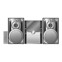
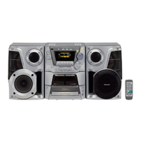
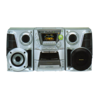
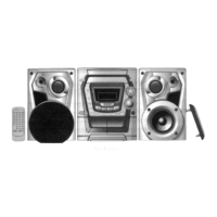
Details the functions of the remote control buttons.

Disassembly and Main Component Replacement Procedures

Disassembly and assembly main unit

Steps for disassembling and assembling the main unit.

Main Component Replacement Procedures

Procedures for replacing major components of the unit.

Disassembly and assembly of the Traverse Unit

Steps for disassembling and assembling the traverse unit.

Disassembly and assembly of the Disc Tray

Steps for disassembling and assembling the disc tray.

Self-Diagnostic Function

Self-diagnostic display

Describes how error codes are displayed on the FL display.

How to enter the Self-Diagnostic Function

Provides instructions on how to activate the self-diagnostic mode.

Cassette Mechanism Test

CD Mechanism Test

To clear all Error code

How to get out from Self-Diagnostic function

Power Amplifier Failure (F61)

Description of Error Code

Error detection for Cassette Mechanism block

Details error codes related to the cassette mechanism.

Error detection for CD/Changer block

Details error codes related to the CD/changer mechanism.

Power Supply related error detection

CD Test Mode Function

How to set CD test mode

Instructions for activating the CD test mode.

CD Automatically Adjustment result indication

Measurements and Adjustments

Cassette Deck Section

Measurement conditions and procedures for the cassette deck.

Head Azimuth Adjustment (Deck 1/2)

Tape Speed Adjustment (Deck 1/2)

Bias and Erase Voltage Check

Bias Frequency Adjustment (Deck 1/2)

Tuner Section

AM-IF Alignment

Procedure for aligning the AM Intermediate Frequency (IF) circuit.

AM-RF Alignment

Alignment Points

Illustration of IC’s, Transistors and Diodes

Terminal Function of IC’s

IC701 (AN8885SBE1) Servo Amplifier

Pin functions for the servo amplifier IC.

IC702 (MN662790RSC) Servo Processor, Digital Signal Processor, Digital Filter, D/A Converter

IC703 (AN8739SBE2) Focus Coil, Tracking Coil, Traverse Motor, Spindle Motor Drive

IC600 (M38B79MFA158) Microprocessor

Block Diagram

Schematic Diagram

CD SERVO CIRCUIT

Schematic for the CD servo system including related ICs.

TUNER CIRCUIT

Schematic for the FM/AM tuner circuits.

MAIN CIRCUIT

Schematic diagram of the main audio processing and control circuits.

PANEL CIRCUIT & SWITCH CIRCUITS

Schematics for front panel and tact switch circuits.

MECHANISM & PCB LAYOUTS

Layouts for Deck, Mechanism, Panel, Power, and CD Servo PCBs.

TRANSFORMER CIRCUITS

Schematics for AC and Sub-Transformer circuits.

Safety Precautions

Printed Circuit Board

Wiring Connection Diagram

Troubleshooting Guide

Parts Location and Replacement Parts List

Deck Mechanism Parts

Location and list of parts for the deck mechanism.

CD Loading Mechanism Parts

Location and list of parts for the CD loading mechanism.

Cabinet Parts

Location and list of parts for the unit's cabinet.

Cabinet Parts List

Detailed list of parts for the cabinet.

Components Lists

Lists of PCBs, ICs, transistors, diodes, resistors, capacitors, etc.

Packing Materials & Accessories Parts List

PACKING MATERIALS

List of materials used for packing.

ACCESSORIES

List of included accessories like remote control and cables.

Packaging

PANEL P.C.B. (REPX0254A)

TACT SWITCH (2) P.C.B. (REP2578A-N)

CD DETACT P.C.B (REP2578A-N)

SPINDLE POSITION P.C.B (REP2578A-N)

Related product manuals