EasyManua.ls Logo

Panasonic SA-AK450GCP User Manual

Panasonic SA-AK450GCP
103 pages
To Next Page IconTo Next Page
Page #1 background imageLoading...
Page #1 background image
n AMPLIFIER SECTION
RMS output power
THD 10%, both channels driven
1 kHz
(Low channel) 115 W per channel (3 )
10 kHz
(High channel) 115 W per channel (3 )
Total Bi-Amp power 460 W
n FM/AM TUNER, TERMINALS SECTION
Preset station FM 20 stations
AM 15 stations
Frequency Modulation (FM)
Frequency range
87.50 to 108.00 MHz (50 kHz step)
Sensitivity 4.0 µV (IHF)
S/N 26 dB 2.2 µV
A
ntenna terminal(s) 75 (unbalanced)
A
mplitude Modulation (AM)
Frequency range 522 to 1629 kHz (9 kHz step)
520 to 1630 kHz (10 kHz step)
Sensitivity
S/N 20 dB (at 999 kHz) 560 µV/m
© 2007 Matsushita Electric Industrial Co. Ltd.. All
rights reserved. Unauthorized copying and
distribution is a violation of law.
SA-AK450GCP
Colour
(K)... Black Type
A
udio performance (Amplifier)
Input sensitivity/Input impedance
A
ux 250mV, 14.7 k
Music Port input jack
Terminal Stereo, 3.5 mm jack
Sensitivity 100 mV, 4.7 k
Phone jack
Terminal Stereo, 3.5 mm jack
MIC jack
Terminal Mono, 3.5 mm jack
Sensitivity 0.7 mV, 680
n CASSETTE DECK SECTION
Track system 4 track, 2 channel
Heads
Record/playback Solid permalloy head
Erasure Double gap ferrite head
Motor DC servo motor
Recording system AC bias 100 kHz
Erase system AC erase 100 kHz
Tape speed 4.8 cm/s
Overall frequency response (+3, -6 dB) at DECK OUT
NORMAL 35 Hz to 14 kHz
CD Stereo System
Notes: This model’s CD mechanism changer unit is CRS1. Please refer to the original Service Manual
(Order No. MD0509368C0) for this mechanism.
Specifications
ORDER NO. MD0703009CE

Table of Contents

Question and Answer IconNeed help?

Do you have a question about the Panasonic SA-AK450GCP and is the answer not in the manual?

Panasonic SA-AK450GCP Specifications

General IconGeneral
RMS Output Power50 W
BluetoothNo
CD PlayerYes
USB PlaybackYes
FM RadioYes
Number of Discs1
Tuner BandsFM
Remote ControlYes
TypeMini HiFi System
Speaker Configuration2.0
Playable MediaCD, CD-R/RW, MP3

Summary

Safety and Handling Precautions

General Service Guidelines

Covers general servicing safety, leak checks, and before-use/repair precautions.

Protection Circuitry and Safety Parts

Explains protection circuit operation and lists critical safety parts for replacement.

Electrostatic Discharge (ESD) Prevention

Traverse Deck Handling Precautions

Laser Diode Safety Precautions

Warning and Legal Restrictions

Product Accessories

Operating Procedures

Main Unit Controls and Operations

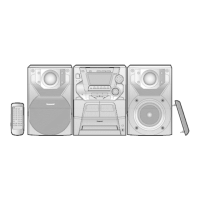
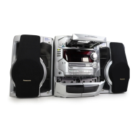
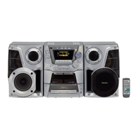
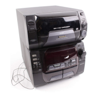
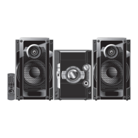
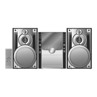
Describes the buttons and functions available on the main unit of the stereo system.

Remote Control Operations

Explains the functions of various buttons on the remote control unit.

New Features

Using Music Port and USB Devices

Guide on connecting and using external audio equipment via Music Port and USB storage devices.

Self-Diagnosis and Special Modes

Service Mode Overview and Tables

Summarizes service modes, special mode tables, and EEPROM checksum procedures.

Reliability Testing and Error Codes

Details on CRS1 reliability testing flow charts and error code tables for troubleshooting.

Assembling and Disassembling Procedures

Disassembly Cautions and Flowchart

Provides general disassembly cautions, a flow chart, and main parts location guide.

Component Disassembly Steps

Covers disassembly of major units like top cabinet, CD changer, rear panel, and various PCBs.

Service Positions and PCB Checks

Checking Specific PCBs

Procedures for checking and repairing main, transformer, panel, deck, and power PCBs.

Deck Mechanism Operation Checks

Cassette Tape Operation Check

Steps for checking deck mechanism operation with and without a cassette tape inserted.

Measurement and Adjustments

Cassette Deck Section Tests

Covers requirements, tape speed adjustment, bias voltage, and frequency checks.

Voltage and Waveform Data

PCB Voltage Charts

Voltage data reference for Deck, Main, Panel, Power, and CD Servo PCBs.

Waveform Chart Reference

Visual representation of waveforms for specific ICs, aiding in troubleshooting.

Wiring Connection Diagram

Block Diagrams

Circuit Block Diagrams

Covers CD Servo, Deck, Main, Panel, Power, and USB/Transformer circuit block diagrams.

Notes on Schematic Diagrams

Schematic Diagrams

Detailed Circuit Schematics

Provides schematics for CD Servo, Main, Panel, Sub Panel, Deck Mechanism, Power, Deck, Transformer, and USB circuits.

Printed Circuit Board Layouts

Component Layouts for Various PCBs

Shows physical component placement on CD Servo, Deck, Main, Panel, Sub Panel, USB, Power, and Transformer PCBs.

Component Identification

IC and Transistor Illustrations

Visual representations of common ICs and transistors used in the unit.

IC Terminal Functions

Detailed pinout and function descriptions for integrated circuits.

Exploded Views and Packaging

Cabinet and Deck Mechanism Parts Location

Exploded views showing parts placement for the main cabinet and the deck mechanism.

Product Packaging Information

Details on how the product is packaged for shipping and handling.

Replacement Parts List

Related product manuals