Do you have a question about the Panasonic SA-AK15 and is the answer not in the manual?
Technical details of the amplifier output and distortion.
Technical details of FM reception sensitivity and performance.
Technical details of AM reception sensitivity and performance.
Technical details of CD playback, sampling frequency, and decoding.
Technical details of tape playback, recording, and frequency response.
Power consumption, supply, dimensions, and weight of the unit.
Guidelines for safely handling the optical pickup and traverse deck.
Methods to prevent damage from static electricity during repair.
Steps for inspecting and checking the main printed circuit boards.
Detailed instructions for taking apart the CD changer mechanism.
Detailed instructions for reassembling the CD changer mechanism.
Step-by-step guide for replacing the traverse deck unit.
Guide for replacing power amplifier IC and specific transistors.
Procedure to activate the diagnostic mode.
Steps to test the cassette deck mechanism and identify errors.
Steps to test the CD mechanism and identify errors.
How to reset or clear any displayed error codes.
Procedure to exit the diagnostic mode.
Specific error indication for power amplifier failure.
Steps to enter the CD test mode for alignment.
How to interpret results from CD automatic alignment tests.
Explanation of specific error codes related to CD alignment results.
Procedure for adjusting the head azimuth on cassette decks.
Procedure for adjusting the tape speed on cassette decks.
How to check bias and erase voltage for cassette decks.
Pin functions for the AN8837SBE1 servo amplifier IC.
Pin functions for the AN8780SBE2 servo driver IC.
Pin functions for the MN662746RPK1 servo processor IC.
Pin functions for the M38197MAA611 system microprocessor IC.
Diagram showing the location of parts for deck 2 mechanism.
Diagram showing the location of parts for deck 1 mechanism.
List of part numbers for the cassette deck mechanism.
List of part numbers for the CD loading mechanism.
List of replacement parts for the unit's exterior and chassis.
List of replacement integrated circuits with part numbers.
List of replacement transistors with part numbers.
List of replacement diodes with part numbers.
List of replacement variable resistors with part numbers.
List of replacement switches with part numbers.
List of replacement connectors with part numbers.
List of replacement relays, fuses, and fuse holders.
List of replacement component assemblies and input/output jacks.
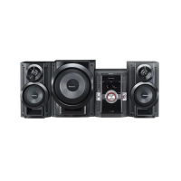
| Type | Mini Hi-Fi System |
|---|---|
| CD Player | Yes |
| Bluetooth | No |
| USB Port | No |
| Number of Discs | 1 |
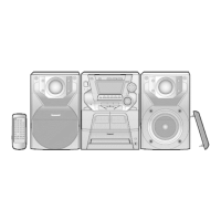
| Remote Control | Yes |
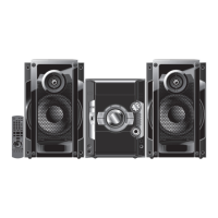
| Speaker Configuration | 2-way speakers |
| Radio Tuner | AM/FM |
| Playable Media | CD, CD-R, CD-RW |
| Speakers | 2 speakers |
| Tape Deck | Dual Tape Deck |