Do you have a question about the Panasonic SA-AK52 and is the answer not in the manual?
Technical details for the audio amplifier, including power output and input sensitivity.
Technical details for the FM tuner, including frequency range and sensitivity.
Technical details for the AM tuner, including frequency range and sensitivity.
Technical details for the CD player, including sampling frequency and response.
Technical details for the cassette deck, including heads and tape speed.
Explanation of the unit's protection circuit and troubleshooting steps.
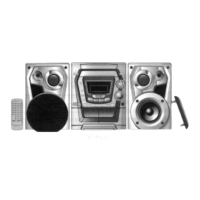
List of accessories provided with the unit.
Methods to prevent electrostatic discharge during servicing.
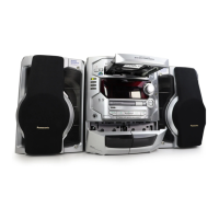
Identification and function of main unit controls.
Identification and function of center console controls.
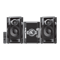
Identification and function of remote control buttons.
Information on a special tool for servicing the mechanism.
Detailed steps for replacing the traverse deck.
Detailed steps for replacing the power amplifier IC.
Step-by-step guide for disassembling and assembling the traverse unit.
Step-by-step guide for disassembling and assembling the disc tray.
Procedures for checking the panel, main, and deck printed circuit boards.
Procedure for checking the power printed circuit board.
Steps for performing troubleshooting with the unit powered on.
How the unit indicates errors via a self-diagnostic display.
Steps to activate the self-diagnostic function.
Test procedure for the cassette mechanism, with error codes.
Test procedure for the CD mechanism, with error codes.
Procedure to clear error codes from the self-diagnostic display.
Steps to exit the self-diagnostic mode.
Specific error indication for power amplifier failure.
List of error codes and their causes for the cassette mechanism.
List of error codes and their causes for the CD/Changer block.
List of error codes and their causes related to power supply issues.
Procedure to set the unit to CD test mode.
How to interpret automatic CD adjustment results.
Procedures for measurements and adjustments on the cassette deck.
Procedure for adjusting the head azimuth on the cassette deck.
Procedure for adjusting tape speed on the cassette deck.
Procedure for checking bias and erase voltage in the cassette deck.
Procedure for adjusting bias frequency on the cassette deck.
Alignment procedure for the AM Intermediate Frequency circuit.
Alignment procedure for the AM Radio Frequency circuit.
Alignment procedure for SW1 Radio Frequency circuit.
Alignment procedure for SW2 Radio Frequency circuit.
Identifies alignment points on the cassette deck and tuner sections.
Pin functions for the Servo Amplifier IC (IC701).
Pin functions for the Servo Processor IC (IC702).
Pin functions for the Traverse Motor Driver IC (IC703).
Pin functions for the Microprocessor IC (IC600).
Schematic of the main and tuner circuits.
Schematics related to the CD unit and panel.
Schematics of the main circuit and audio sound processor.
Schematics of buffer amplifiers and audio muting circuits.
Schematic of the power circuit and speaker output stages.
Schematic of component connections and switch functions.
Schematic of the CD servo circuit.
Schematic of the servo processor and digital signal processing.
Schematic of FM/AM IF and PLL frequency synthesizer circuits.
Schematic of the main circuit and audio processor connections.
Schematic of motor drive and TPS circuits for cassette decks.
Schematic of power supply control and speaker output stages.
Schematic of the panel controls and remote sensor.
Schematic showing connections between various modules.
Schematic of the cassette deck circuit.
Schematic of motor drive and TPS circuits for cassette decks.
Schematic of the power supply section, including regulators and protection.
Schematic of the AC transformer and voltage selector circuits.
Schematic of the voltage selector mechanism.
Schematic of the sub-transformer circuit.
Layout of the CD Servo Printed Circuit Board.
Layout of the Main and Tuner Printed Circuit Board.
Layout of the Panel Printed Circuit Board.
Layout of the Headphone Printed Circuit Board.
Layout of the Microphone Printed Circuit Board.
Layout of the Tact Switch (1) and (2) Printed Circuit Boards.
Layout of the Mechanism (Deck 1) and (Deck 2) Printed Circuit Boards.
Layout of the Tuner Pack Printed Circuit Board.
Layout of the CD Loading Printed Circuit Board.
Layout of the CD Detect Printed Circuit Board.
Layout of the Spindle Position Printed Circuit Board.
Layout of the Deck Printed Circuit Board.
Layout of the Power Printed Circuit Board.
Layout of the AC Transformer Printed Circuit Board.
Layout of the Sub-Transformer Printed Circuit Board.
Exploded view showing the location of deck mechanism parts.
Detailed list of parts for the cassette deck mechanism.
Exploded view showing the location of CD loading mechanism parts.
Detailed list of parts for the CD loading mechanism.
Exploded view showing the location of cabinet parts and PCBs.
List of printed circuit boards with part numbers.
List of integrated circuits with part numbers.
List of transistors with part numbers.
List of diodes with part numbers.
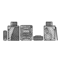
Diagram illustrating how the unit is packaged.
| Brand | Panasonic |
|---|---|
| Model | SA-AK52 |
| Category | Stereo System |
| Language | English |