EasyManua.ls Logo

Panasonic SA-AK58 User Manual

Panasonic SA-AK58
157 pages
To Next Page IconTo Next Page
Page #1 background imageLoading...
Page #1 background image
ORDER No.MD0005087C3
CD Stereo System
SA-AK58
Colour
(S) ................. Silver Type
Areas
(GN) ............... Oceania.
TAPE SECTION : AR2 MECHANISM SERIES
CD SECTION : RAE0152Z-M TRAVERSE DECK SERIES
SYSTEM : SC-AK58
SPECIFICATIONS
Specifications
1
Question and Answer IconNeed help?

Do you have a question about the Panasonic SA-AK58 and is the answer not in the manual?

Panasonic SA-AK58 Specifications

General IconGeneral
BrandPanasonic
ModelSA-AK58
CategoryStereo System
LanguageEnglish

Summary

Specifications

System Specifications

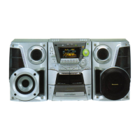
Detailed technical specifications for the CD Stereo System SA-AK58.

Sectional Specifications

Amplifier, Tuner, and Cassette Deck Specs

Details on amplifier, FM/AM tuner, and cassette deck performance metrics.

CD Section Specifications

Technical details for the CD playback mechanism.

General Information and Accessories

General System Information

Power supply, consumption, dimensions, weight, and system configuration.

Repair and Protection Procedures

Before Repair Safety Steps

Steps for safely discharging capacitors and checking current consumption before repair.

Protection Circuitry Troubleshooting

Procedures for addressing sound issues and protection circuit activation.

Traverse Deck Handling Precautions

Traverse Deck Handling and Grounding

Precautions for handling the traverse deck and preventing electrostatic discharge.

Traverse Deck Replacement and Laser Safety

Laser Diode Safety Precautions

Warning about hazardous radiation exposure from laser components.

Location of Controls

Remote Control Transmitter Controls

Operation Checks and Component Replacement

P.C.B. Checking Procedures

Checking the Main P.C.B.

Steps for accessing and checking the main printed circuit board.

Disassembly Procedures

CD Changer Assembly and Disc Tray Disassembly

Steps to disassemble the CD changer unit and disc tray ornament.

CD Changer Unit Disassembly

Disassembly for the CD Changer Unit

Steps to remove the CD changer unit from the assembly.

Unit Operational Condition Checks

Checking Unit Operational Condition and CD Unit Setting

General steps for checking unit operation and initial CD unit setup.

CD Servo P.C.B. Checking

Checking the CD Servo P.C.B.

Procedure to check the CD servo printed circuit board.

P.C.B. Checking Procedures

Checking Dolby Pro Logic, FL, and Cassette Control P.C.B.s

Checking procedures for specific printed circuit boards.

Power Supply P.C.B. Checking

Checking the Power Supply P.C.B.

Procedure for checking the power supply printed circuit board.

Traverse Deck Assembly Replacement

Replacement for the Traverse Deck Assembly

Steps to replace the traverse deck assembly.

Disc Tray Replacement

Replacement for the Disc Tray

Procedure for replacing the disc tray component.

Mechanism Base Drive Unit Disassembly/Reassembly

Disassembly and Reassembly for Mechanism Base Drive Unit

Detailed steps for disassembling and reassembling the drive unit.

Component Replacement Procedures

Replacement for the Motor Assembly

Steps for replacing the motor assembly.

Pinch Roller and Head Block Replacement

Replacement for Pinch Roller Assembly and Head Block

Procedures for replacing the pinch roller and head block.

Belt and Motor Assembly Replacement

Replacement for CD Motor, Capstan Belts, and Winding Belt

Steps for replacing various belts and the CD motor assembly.

Mechanism P.C.B. and Cassette Lid Replacement

Replacement for Component Parts on Mechanism P.C.B.

Procedure for replacing components on the mechanism PCB.

Replacement for Cassette Lid Assembly

Steps for replacing the cassette lid assembly.

Tape Trouble Measurement

Measure for Tape Trouble

Procedure for measuring and diagnosing tape-related issues.

Cassette Mechanism Self-Operation Checks

Operation Check with Cassette Tape

Checking cassette mechanism operation using a tape.

Self-Diagnostic Display Function

Operation Check without Cassette Tape

Checking cassette mechanism operation without a tape.

Cassette Mechanism Test and Error Codes

Cassette Mechanism Test

Procedure for testing the cassette mechanism and identifying error codes.

Error Code Description and CD Mechanism Test

CD Mechanism Test

Procedure for testing the CD mechanism and identifying error codes.

Description of Error Codes

Detailed descriptions and problem conditions for detected error codes.

Error Detection Details

Error Detection for CD/Changer Block

List of error codes and conditions for the CD/Changer.

Error Detection for Cassette Mechanism Block

List of error codes and conditions for the Cassette Mechanism.

CD Test Mode Function

CD Test Mode Operation

How to set and use the CD test mode for checking the unit.

Measurement and Adjustments

Tuner Section Measurement Instruments

List of instruments and tools for tuner section adjustments.

AM IF Adjustment

Procedure for adjusting the AM Intermediate Frequency.

AM RF Adjustment

AM RF Adjustment Procedure

Steps for adjusting the AM Radio Frequency.

Cassette Deck Section Measurements

Cassette Deck Measuring Instruments

Instruments and special tools for cassette deck measurements.

Head Azimuth Adjustment (Deck 1/2)

Procedure for adjusting the head azimuth for both cassette decks.

Tape Speed Adjustment (Deck 1/2)

Tape Speed Adjustment Procedure

Steps for adjusting the tape speed on both decks.

Cassette Deck Bias and Voltage Checks

Bias OSC Frequency Adjustment (Deck 2)

Procedure for adjusting bias oscillator frequency on Deck 2.

Bias Voltage Check

Procedure for checking bias voltage using different tape types.

Erase Voltage Check

Procedure for checking erase voltage.

Adjustment Points and Component Illustrations

Illustration of ICs, Transistors, and Diodes

Visual identification of key electronic components.

Schematic Diagram Notes

Important notes regarding the schematic diagrams.

IC Safety and Terminal Functions

Terminal Function of ICs

Details on the function of pins for various integrated circuits.

IC600 Terminal Functions

Pinout and function description for IC600 (System Control/FL Driver).

IC Terminal Functions

IC701 (AN8839NSBE2) Terminal Functions

Pinout and function details for the Servo Amplifier IC701.

IC Terminal Functions

IC702 (MN662790RSC) Terminal Functions

Pinout and function details for the Servo Processor/DSP IC702.

IC Terminal Functions

IC703 (AN8739SBE2) Terminal Functions

Pinout and function details for the Motor Drive IC703.

Replacement Parts List

Cabinet Parts Location

Mechanism Parts Location

CD Mechanism Parts Location

Packaging Details

Electrical Parts Location Diagrams

Mechanism P.C.B. (Deck 1) Location

Diagram showing component placement on the Deck 1 mechanism PCB.

Mechanism P.C.B. (Deck 2) Location

Diagram showing component placement on the Deck 2 mechanism PCB.

P.C.B. Component Location Diagrams

Operation P.C.B. (1) Component Location

Diagram showing component placement on Operation P.C.B. (1).

Operation P.C.B. (2) Component Location

Diagram showing component placement on Operation P.C.B. (2).

Power Amplifier P.C.B. Component Location

Power Amplifier P.C.B. Component Location

Diagram detailing component placement on the Power Amplifier P.C.B.

Circuit Board Component Locations

DPL P.C.B. Component Location

Diagram showing component placement on the Dolby Pro Logic P.C.B.

AC IN P.C.B. Component Location

Diagram showing component placement on the AC IN P.C.B.

Power Transformer and Motor P.C.B. Locations

Power Transformer P.C.B. Component Location

Diagram for component placement on the Power Transformer P.C.B.

Loading Motor P.C.B. Component Location

Diagram for component placement on the Loading Motor P.C.B.

Schematic Diagram-1: CD Servo Circuit

Schematic Diagram-2: Servo Processor

Schematic Diagram-3: Tuner Circuit

Main (Tuner) Circuit Diagram

Schematic for the main tuner section, including FM front end.

Schematic Diagram-4: IF Amplifier

FM/AM IF Amplifier and Decoder Circuit Diagram

Schematic for IC101, showing IF amplification and decoding.

Schematic Diagram-5: Mechanism Control

Mechanism Control Circuit Diagram

Schematic illustrating the mechanism control functions and components.

Schematic Diagram-6: PB/REC Amplifier

Playback/Record Amplifier Circuit Diagram

Schematic for IC1101 and IC1108, detailing PB/REC amplification.

Schematic Diagram-7: Mechanism Interface

Mechanism (Deck2) Interface Circuit Diagram

Schematic for Deck 2 mechanism interface components.

Mechanism (Deck1) Interface Circuit Diagram

Schematic for Deck 1 mechanism interface components.

Schematic Diagram-8: Motor Drive and Control

Motor Drive and Control Circuit Diagram

Schematic showing motor drive circuits and system control connections.

Schematic Diagram-9: Dolby Pro Logic Control

Dolby Pro Logic Control Circuit Diagram

Schematic for IC801, detailing Dolby Pro Logic control functions.

Schematic Diagram-10: Graphic Equalizer and CD Control

Graphic Equalizer and CD Control Circuit Diagram

Schematic for IC303 and IC600, covering EQ and CD control.

Schematic Diagram-11: System Control and FL Drive

System Control and FL Drive Circuit Diagram

Schematic for IC600, showing system control and FL display drive.

Schematic Diagram-12: FL Circuit

FL Circuit Diagram

Detailed schematic of the Front-Line (FL) display circuit.

Schematic Diagram-13: Power Transformer and AC Input

Power Transformer Circuit Diagram

Schematic for the power transformer and related components.

AC Input Circuit Diagram

Schematic illustrating the AC input and power supply connections.

Schematic Diagram-14: Motor and Switch Circuits

Loading Motor Circuit Diagram

Schematic showing the loading motor control circuit.

Clamp Switch P.C.B. Diagram

Schematic for the clamp switch printed circuit board.

Bottom Switch P.C.B. Diagram

Schematic for the bottom switch printed circuit board.

Schematic Diagram-15: Main Control Circuit

Main (Control) Circuit Diagram

Schematic detailing the main control functions and interconnections.

Schematic Diagram-16: IF Amplifier and Equalizer

IF Amplifier and Graphic Equalizer Circuit Diagram

Schematic for IC301 and IC303, covering IF amp and EQ functions.

Schematic Diagram-17: Main Control and Speaker Output

Main (Control) Circuit and Speaker Output Connections

Schematic for main control and speaker output routing.

Schematic Diagram-18: Power Amplifier

Power Amplifier Circuit Diagram

Detailed schematic of the power amplifier section (IC500).

Schematic Diagram-19: Regulator and Protection

Regulator and Protection Circuit Diagram

Schematic for regulators (IC501) and protection circuits.

Schematic Diagram-20: Power Transformer and AC Input

Power Transformer Circuit Diagram

Schematic for the power transformer and associated components.

AC Input Circuit Diagram

Schematic illustrating the AC input and power supply connections.

Component Illustrations

Electrical Parts Location Diagrams

CD Servo P.C.B. Component Location

Diagram showing component layout on the CD Servo P.C.B.

Clamp Switch P.C.B. Component Location

Diagram showing component layout on the Clamp Switch P.C.B.

Bottom Switch P.C.B. Component Location

Diagram showing component layout on the Bottom Switch P.C.B.

Electrical Parts Location Diagrams

Mechanism Control P.C.B. Component Location

Diagram showing component layout on the Mechanism Control P.C.B.

Electrical Parts Location Diagrams

Main P.C.B. Component Location

Diagram showing component layout on the Main P.C.B.

Electrical Parts Location Diagrams

FM Front End P.C.B. Component Location

Diagram showing component layout on the FM Front End P.C.B.

Electrical Parts Location Diagrams

FL P.C.B. Component Location

Diagram showing component layout on the Front-Line (FL) P.C.B.

Electrical Parts Location Summary

Related product manuals