Do you have a question about the Panasonic SA-AK70 and is the answer not in the manual?
Detailed specifications for the amplifier stage, including power output and harmonic distortion.
Technical details for the FM tuner, covering frequency range and sensitivity.
Technical details for the AM tuner, covering frequency range and sensitivity.
Specifications for the cassette deck, including track system and heads.
Information on tape speed and frequency response for different tape types.
Specifications related to the CD playback, including sampling frequency and decoding.
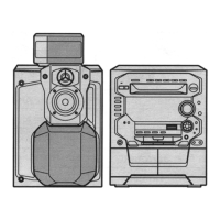
General specifications and notes for the system, including power supply and dimensions.
Schematic diagram of the optical pickup, detailing laser diode and photodetector connections.
Circuit diagram for the servo amplifier, showing connections to pickup and motors.
Schematic for the FM front end, including RF amplifier and mixer stages.
Circuit diagram for the mechanism control of Deck 2, including head select and bias OSC.
Circuit diagram for the mechanism control of Deck 1, including head select and bias OSC.
Overview of the main system control and interface circuits, detailing internal connections.
Circuit details for the slide motor, including speed sensor functionality.
Circuitry related to photo sensors used for mechanism detection.
Circuit details for CD loading and spindle motors, including drive control.
Detailed schematic of the main system circuit, covering interface and control signals.
Block diagram illustrating the CD changer's operational flow and interconnections.
Functional block for the optical pickup unit, showing laser and detector systems.
Block representation of the servo amplifier's role in disc control.
Block diagram of the servo processor, handling digital signal processing and D/A conversion.
Functional block for the FM/AM Intermediate Frequency amplifier and detector.
Block diagram of the PLL synthesizer for tuning and frequency control.
Wiring details for the AC input stage on the power circuit board.
Wiring connections for the power supply unit.
Wiring interconnections between the mechanism control and other boards.
| Type | Mini Hi-Fi System |
|---|---|
| CD Player | Yes |
| Radio Tuner | Yes |
| Bluetooth | No |
| USB Port | No |
| Playback Formats | CD, CD-R, CD-RW |
| Tuner Bands | AM/FM |
| Number of Discs | 5 |
| Tuner | Digital Synthesizer |
| Equalizer | Yes |
| Inputs | AUX |
| Cassette Deck | Yes |