EasyManua.ls Logo

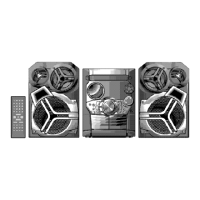
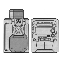
Panasonic SA-AK33 Service Manual

Panasonic SA-AK33
26 pages
To Next Page IconTo Next Page
Page #1 background imageLoading...
Page #1 background image
http://servis-manual.com/
Service Manual
TOP NEXT
ORDER NO. MD0011177C1
A6
CD Stereo System
l
SA-AK33
Chassis
Colour
(S)... Silver Type
Area
(P)... U.S.A.
(PC)... Canada
TAPE SECTION :
SG2 MECHANISM SERIES
CD SECTION :
RAE0152Z-3 TRAVERSE DECK SERIES
Specifications
AMPLIFIER SECTION
Power output
THD 10% Total harmonic distortion
(HIGH) 35-40 W per channel (6Ω)
(LOW) 85-90 W per channel (6Ω)
(TOTAL) 120-130 W per channel
Input sensitivity
AUX 250 mV
Input Impedance
AUX 13 kΩ
FM TUNER SECTION
Frequency range 87.9 - 107.9 MHz (200 kHz steps)
87.5 - 108.0 MHz (100 kHz steps)
Sensitivity 2.5μV (IHF)
S/N 26 dB 2.2μV
Antenna terminal(s) 75Ω (unbalanced)
AM TUNER SECTION
Frequency range 520 - 1710 kHz (10 kHz steps)
Sensitivity
S/N 20 dB (at 1000 kHz) 560μV/m
CASSETTE DECK SECTION
Track system 4 track, 2 channel
Heads
Record/playback Solid permalloy head
Erasure Double gap ferrite head
Motor DC servo motor
Recording system AC bias 100 kHz
Erasing system AC erase 100 kHz
Tape speed 4.8 cm/s
Frequency response (+3 dB, -6 dB at DECK OUT)
NORMAL (TYPE I) 35 Hz - 14 kHz
HIGH (TYPE II) 35 Hz - 14 kHz
S/N 50 dB (A weighted)
Wow and flutter 0.18% (WRMS)
Fast forward and rewind time Approx. 120 seconds with
Question and Answer IconNeed help?

Do you have a question about the Panasonic SA-AK33 and is the answer not in the manual?

Panasonic SA-AK33 Specifications

General IconGeneral
BrandPanasonic
ModelSA-AK33
CategoryStereo System
LanguageEnglish

Summary

Specifications

Amplifier Section Specifications

Details the power output, input sensitivity, and impedance of the amplifier.

FM Tuner Section Specifications

Specifies frequency range, sensitivity, and antenna terminal for FM reception.

AM Tuner Section Specifications

Outlines frequency range and sensitivity for AM reception.

Cassette Deck Section Specifications

Lists tape system, heads, motor, frequency response, and wow/flutter for the cassette deck.

Self-diagnostic Display Function

Entering Self-Diagnostic Function

Cassette Mechanism Test Procedure

CD Mechanism Test Procedure

Clearing All Error Codes

Exiting Self-Diagnostic Function

Power Amplifier Failure (F61) Indication

Cassette Mechanism Error Detection

CD/Changer Block Error Detection

Power Supply Error Detection

Setting CD Test Mode

CD Automatic Adjustment Result Indication

Troubleshooting Guide

CD Servo Circuit Schematic

CD Servo Processor and DAC Schematic

Cassette Deck Circuit Schematic

Mechanism Circuit Schematic (Deck 1)

Main Circuit Schematic

Main Circuit Components Schematic

Power Circuit Schematic

Panel Circuit Schematic

Tact Switch (1) Circuit

Schematic of the first tactile switch circuit, including remote control sensor and LEDs.

Tact Switch (2) Circuit

Schematic of the second tactile switch circuit, detailing switches and I/O expander connections.

Main Processor and Interface Schematic

Power Circuit Schematic (Continued)

Transformer and Motor Drive Circuits

CD Loading Circuit

Schematic of the CD loading motor drive and control circuitry.

Sub-Transformer Circuit

Schematic diagram for the sub-transformer circuit.

Related product manuals