Do you have a question about the Panasonic SA-AK340GCP and is the answer not in the manual?
Details of the amplifier's output power and THD characteristics.
Specifications for FM/AM tuning, frequency range, sensitivity, and terminals.
Technical details of the cassette deck, including track system, heads, and speed.
Information about the type of discs supported by the unit.
General advice for servicing and handling the equipment safely.
Instructions for setting the voltage selector and initial precautions.
Procedures for safe repair, including discharging capacitors and avoiding short circuits.
Explanation of the protection circuitry and when it might operate.
Techniques to prevent damage to sensitive electronic components from static electricity.
Specific instructions for safely handling the traverse deck and its components.
Warnings and precautions related to the unit's laser diode.
Details about lead-free solder, including melting points and handling.
An overview of the CRS1 five-disc CD changer mechanism.
Description of the Music Port feature for connecting portable audio devices.
List of accessories provided with the unit, illustrated with images.
Instructions for operating the main unit controls and functions.
Guide to using the remote control for various operations.
Table detailing various diagnostic and test modes with their key operations.
List of error codes, their diagnosis, and remarks for troubleshooting.
Important safety notes and warnings before disassembling the unit.
A flowchart illustrating the sequence of disassembly steps for internal inspection.
Diagram showing the location of major internal components within the unit.
Step-by-step instructions for removing the top cabinet.
Instructions for removing the rear panel of the unit.
Procedure for removing the CRS1 CD changer unit.
Steps to remove the main printed circuit board.
Steps to remove the transformer printed circuit board.
Instructions for removing the power printed circuit board.
Steps to remove the front panel unit.
Procedure for removing the panel printed circuit board.
Steps to disassemble the cassette deck mechanism unit.
Instructions for removing the deck printed circuit board.
Procedure for removing the traverse unit.
Steps to remove the optical pickup unit from the CD mechanism.
Procedure for disassembling the deck mechanism itself.
Steps for disassembling the pinch roller and head block.
Steps for disassembling motor assembly, belts, and winding belt.
Steps for replacing the cassette lid.
Instructions for resolving tape jamming issues.
Lists necessary fixtures and tools for servicing the unit.
Procedures for checking and repairing the main P.C.B.
Procedures for checking and repairing the transformer P.C.B.
Procedures for checking and repairing multiple P.C.Bs.
Procedures for checking and repairing the power P.C.B.
Details on adjusting tape speed, bias voltage, and bias frequency.
Procedures for aligning the AM-IF and AM RF circuits.
Locations for making adjustments on the main tuner P.C.B.
Reference voltage values for CD Servo and Main P.C.Bs.
Reference voltage values for Power and Transformer P.C.Bs.
Visual representations of signal waveforms at various test points.
Important notes and safety precautions related to schematic diagrams.
Schematic diagram of the CD servo control circuit.
Schematic diagram of the main unit and tuner circuitry.
Schematic diagram of the main control and processing circuits.
Schematic diagram of the front panel control circuitry.
Schematic diagram of the power transformer and related components.
Schematic diagram of the unit's power supply circuits.
Schematic diagrams for the cassette deck and its mechanism control.
Layout diagram of the CD servo printed circuit board.
Layout diagram of the main printed circuit board.
Layout diagram of the front panel printed circuit board.
Layout diagram of the transformer printed circuit board.
Layout diagram of the power printed circuit board.
Layout diagrams for the deck and deck mechanism PCBs.
Pin terminal functions for IC7001 (Servo Processor, Digital Signal Processor).
Pin terminal functions for IC7002 (4CH Drive).
Pin terminal functions for IC2801 (System Microprocessor).
Exploded view showing the location of cabinet parts.
Exploded view showing the location of deck mechanism parts.
Diagram illustrating the packaging of the unit and accessories.
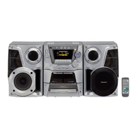
| Brand | Panasonic |
|---|---|
| Model | SA-AK340GCP |
| Category | Stereo System |
| Language | English |



 Loading...