EasyManua.ls Logo

Panasonic SA-AK350GCP User Manual

Panasonic SA-AK350GCP
107 pages
To Next Page IconTo Next Page
Page #1 background imageLoading...
Page #1 background image
n AMPLIFIER SECTION
RMS output power
THD 10%, both channels driven
1 kHz
(Low channel) 112.5 W per channel (3 )
10 kHz
(High channel) 112.5 W per channel (3 )
Total Bi-Amp power 450 W
n FM/AM TUNER, TERMINALS SECTION
Preset station FM 20 stations
AM 15 stations
Frequency Modulation (FM)
Frequency range
87.50 to 108.00 MHz (50 kHz steps)
Sensitivity 4.0 µV (IHF)
S/N 26 dB 2.2 µV
A
ntenna terminal(s) 75 (unbalanced)
A
mplitude Modulation (AM)
Frequency range 522 to 1629 kHz (9 kHz step)
520 to 1630 kHz (10 kHz step)
Sensitivity
S/N 20 dB (at 999 kHz) 560 µV/m
A
udio performance (Amplifier)
Input Sensitivity/ Input Impedance
© 2007 Matsushita Electric Industrial Co. Ltd.. All
rights reserved. Unauthorized copying and
distribution is a violation of law.
SA-AK350GCP
Colour
(S)... Silver Type
A
ux 250 mV, 14.7 k
Music Port input jack
Terminal Stereo, 3.5 mm jack
Sensitivity 100 mV, 4.7 k
Phone jack
Terminal Stereo, 3.5 mm jack
Mic jack
Terminal Mono, 3.5 mm jack
Sensitivity 0.7 mV, 680
n CASSETTE DECK SECTION
Track system 4 track, 2 channel
Heads
Record/playback Solid permalloy head
Erasure Double gap ferrite head
Motor DC servo motor
Recording system AC bias 100 kHz
Erasing system AC erase 100 kHz
Tape speed 4.8 cm/s
Overall frequency response (+3, -6 dB) at DECK OUT
NORMAL 35 Hz to 14 kHz
S/N ratio 50 dB (A weighted)
Wow and flutter 0.18 % (WRMS)
Fast forward and rewind time Approx. 120 seconds with
CD Stereo System
Notes: This model’s CD mechanism changer unit is CRS1. Please refer to the original Service Manual
(Order No. MD0509368C0) for this mechanism.
Specifications
ORDER NO. MD0704047CE

Table of Contents

Question and Answer IconNeed help?

Do you have a question about the Panasonic SA-AK350GCP and is the answer not in the manual?

Panasonic SA-AK350GCP Specifications

General IconGeneral
TypeMini Hi-Fi System
Number of Channels2
BluetoothNo
USB PlaybackYes
FM TunerYes
Tuner BandsFM
Dimensions (W x H x D)250 x 330 x 275 mm
CD PlayerYes
Speaker Configuration2-Way
Disc CompatibilityCD
Playable MediaCD
Audio formatsMP3

Summary

Product Specifications

Disc and USB Playback Specifications

Safety Precautions and Guidelines

General Service Guidelines

General guidelines for servicing, including lead dress, protective devices, and leakage current checks.

Leakage Current Measurement Procedures

Procedures for performing cold and hot checks to measure leakage current in the equipment.

Pre-Use and Pre-Repair Precautions

Instructions for voltage selector setting, capacitor discharge, and pre-repair precautions.

Safety Critical Component Identification

List and identification of safety-critical components that require specific replacement parts.

Electro Static Discharge (ESD) Prevention

Handling Sensitive Electronic Devices

Techniques to prevent damage to ES devices from electrostatic discharge during handling and repair.

Traverse Deck Handling Precautions

Traverse Deck Handling Procedures

Precautions for handling the traverse deck (optical pickup) to prevent static breakdown and damage.

Grounding for ESD Prevention

Methods for grounding to prevent electrostatic breakdown, including human body and work table grounding.

Laser Diode Safety Precautions

Laser Diode Safety Guidelines

Precautions for handling the laser diode, including avoiding disassembly and direct viewing.

Self-Diagnosis and Special Mode Settings

Service Mode Summary Table

Table summarizing service modes, button combinations, applications, and notes for diagnostics.

Special Mode Table 1

Details of special modes, their FL display, and key operations for diagnostics.

Error Code Display Information

Error Code Table for Deck Mechanism

Table listing error codes for the deck mechanism, their contents, display, and remarks.

Assembling and Disassembling Procedures

Assembling and Disassembling Cautions

General cautions and a list of disassembly sections for servicing the unit.

Component Disassembly Procedures

PCB Disassembly Procedures

Panel and Switch PCB Disassembly

USB and Deck Mechanism Unit Disassembly

Deck PCB and Traverse Unit Disassembly

Deck Mechanism Repair Procedures

Pinch Roller and Head Block Replacement

Instructions for replacing the pinch roller and head block in the deck mechanism.

Cassette Lid and Tape Jam Rectification

Rectification for Tape Jam Problem

Procedure for resolving tape jam issues, including rotating the flywheel.

Service Fixtures, Tools, and Positions

Checking and Repairing of Main P.C.B.

Procedure for checking and repairing the main PCB, including top cabinet removal.

PCB Checking and Repair Procedures

Checking and Repairing of Transformer P.C.B.

Procedure for checking and repairing the transformer PCB, including top cabinet removal.

Checking and Repairing of Panel, Deck & Deck Mechanism P.C.B.

Procedures for checking and repairing Panel, Deck, and Deck Mechanism PCBs.

Power PCB Checking and Repair

Checking and Repairing of Power P.C.B.

Procedures for checking and repairing the power PCB, including CD changer unit disassembly.

Deck Mechanism Operation Checks

Operation Check with Cassette Tape

Procedure for checking deck mechanism operation with a cassette tape inserted.

Operation Check without Cassette Tape

Procedure for checking deck mechanism operation without a cassette tape.

Measurement and Adjustments

Cassette Deck Section Measurements

Requirements, unit setting, and preparations for cassette deck measurements and adjustments.

Tape Speed Adjustment Procedure

Procedure for adjusting the tape speed, including product reference values and adjustment range.

Cassette Deck Section Checks

Bias Voltage Check

Procedure for checking the bias voltage in the cassette deck section.

Bias Frequency Check

Procedure for checking the bias frequency in the cassette deck section.

Voltage and Waveform Charts

USB P.C.B. Voltage and Waveform Chart

Voltage and waveform chart for the USB PCB, providing reference information for diagnostics.

CD Servo P.C.B. Voltage and Waveform Chart

Voltage and waveform chart for the CD Servo PCB, offering reference data for troubleshooting.

Deck PCB Voltage and Waveform Charts

Main and Panel PCB Voltage and Waveform Charts

Power and Transformer PCB Voltage and Waveform Charts

Waveform Charts for Diagnostics

Wiring Connection Diagram

Wiring Connection Diagram

Diagram illustrating the wiring connections between major PCBs and components of the unit.

Block Diagrams Overview

Main System Block Diagram

Schematic Diagrams

Main Circuit Schematic

IC Terminal Functions

IC Terminal Functions Continued

Replacement Parts List

Comprehensive Replacement Parts List

Comprehensive list of replacement parts with part numbers, descriptions, and remarks.
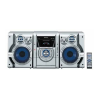
Related product manuals