EasyManua.ls Logo

Panasonic SA-AK310GC User Manual

Panasonic SA-AK310GC
185 pages
To Next Page IconTo Next Page
Page #1 background imageLoading...
Page #1 background image
Service Manual
TOP NEXT
ORDER NO. MD0212275C3
CD Stereo System
SA-AK310GC
SA-AK310GN
Colour
(S)... Silver Type
TAPE SECTION :
SG-2W MECHANISM SERIES
Specifications
AMPLIFIER SECTION
Power output
10% Total harmonic distortion
1kHz, both channels driven
(Low channel) 55 W per channel (6 )
10kHz, both channels driven
(High channel) 55 W per channel (6 )
Total Bi-Amp power 110 W per channel
Input sensitivity
AUX 250 mV
Input Impedance
AUX 13.3 k
FM TUNER SECTION
Frequency range 87.50 - 108.00 MHz (50 kHz steps)
Sensitivity 2.5µ V (IHF)
S/ N 26 dB 2.2µ V
Antenna terminal(s) 75 (unbalanced)
AM TUNER SECTION
Frequency range 522 - 1629 kHz (9 kHz steps)
520 - 1630 kHz (10 kHz steps)

Table of Contents

Question and Answer IconNeed help?

Do you have a question about the Panasonic SA-AK310GC and is the answer not in the manual?

Panasonic SA-AK310GC Specifications

General IconGeneral
CD PlayerYes
BluetoothNo
FM TunerYes
USB PortYes
Weight5.5 kg
Number of Channels2
TunerFM
USB PlaybackYes
Playback FormatsCD, CD-R, CD-RW
Speaker Type2-Way
RMS Output Power300 W

Summary

Product Specifications

Amplifier Section Specifications

Details power output, input sensitivity, and impedance for the amplifier.

FM Tuner Section Specifications

Details frequency range and sensitivity for the FM tuner.

AM Tuner Section Specifications

Details frequency range for the AM tuner.

Cassette Deck Section Specifications

Details track system, heads, motor, recording system, tape speed, and frequency response.

CD Section Specifications

Details sampling frequency, decoding, laser type, number of channels, and frequency response.

General Specifications

Details power supply voltage, power consumption, dimensions, and mass.

System Configuration Details

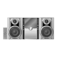
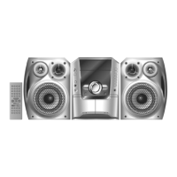
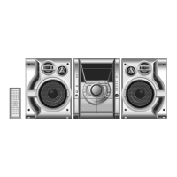
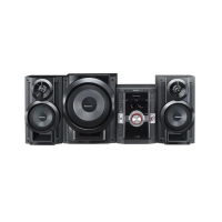
Lists the main unit and speaker model names for different regions.

1 Before Use Instructions

2 Before Repair and Adjustment Guidelines

3 Protection Circuitry Explanation

4 Included Accessories

5 Operation Procedures Overview

6 Handling Precautions For Traverse Deck

Traverse Deck Handling Precautions

Precautions for handling the traverse deck and optical pickup.

Electrostatic Breakdown Prevention Measures

Guidelines for grounding and preventing static discharge during handling.

7 Operation Checks and Component Replacement Procedures

7.1 Main P.C.B. Checking Steps

Steps to check the main printed circuit board.

7.2 CD Changer Disassembly Procedures

Procedures for disassembling the CD changer unit.

7.3 Unit Operational Condition Checking

Steps to check the operational condition of the unit.

7.4 Main Component Replacement Steps

Procedures for replacing major components.

7.5 Disc Tray Replacement Guide

Steps for replacing the disc tray mechanism.

7.6 Mechanism Base Drive Unit Disassembly and Reassembly

Procedures for disassembling and reassembling the mechanism base drive unit.

7.7 Motor Assembly Replacement Instructions

Steps for replacing the motor assembly.

7.8 Pinch Roller and Head Block Replacement

Procedures for replacing the pinch roller assembly and head block.

7.9 Deck Motor and Belt Replacement

Steps for replacing deck motor and belts.

7.10 CD Motor and Belt Replacement

Steps for replacing CD motor and belts.

7.11 Cassette Lid Assembly Replacement

Procedures for replacing the cassette lid assembly.

7.12 Tape Trouble Measurement and Solutions

Steps for diagnosing and resolving tape-related issues.

8 Precaution of Laser Diode Safety

9 Self-Diagnostic Function

9.1 Self-Diagnostic Display Function

Explains the self-diagnostic display function and error codes.

9.2 Entering the Self-Diagnostic Function

Instructions on how to access the self-diagnostic function.

9.3 Cassette Mechanism Test Procedures

Procedures for testing the cassette mechanism for specific error codes.

9.4 CD Mechanism Test Procedures

Procedures for testing the CD mechanism for specific error codes.

9.5 Clearing All Error Codes

Instructions on how to clear all error codes.

9.6 Exiting the Self-Diagnostic Function

Steps to exit the self-diagnostic function.

9.7 Power Amplifier Failure Diagnosis

Information on diagnosing power amplifier failure (F61).

10 Description of Error Codes

10.1 Cassette Mechanism Error Detection

Lists and describes error codes for the cassette mechanism.

10.2 CD Changer Error Detection

Lists and describes error codes for the CD changer.

10.3 Power Supply Related Error Detection

Describes error detection related to the power supply.

11 CD Test Mode Functionality

11.1 How to Set CD Test Mode

Instructions on how to set the CD test mode.

11.2 CD Automatic Adjustment Result Indication

How to interpret the results of CD automatic adjustment.

12 Measurements and Adjustments

12.1 Cassette Deck Section Measurements

Measurement conditions, instruments, and test tape for cassette deck.

12.1.1 Tape Speed Adjustment (Deck 1 / 2)

Procedure for adjusting tape speed on decks.

12.1.2 Bias and Erase Voltage Check

Procedure for checking bias and erase voltage.

12.1.3 Bias Frequency Adjustment (Deck 1 / 2)

Procedure for adjusting bias frequency.

12.2 Tuner Section Measurements

Measurements and adjustments for the tuner section.

12.2.1 AM-IF Alignment Procedure

Procedure for AM intermediate frequency alignment.

12.2.2 AM RF Adjustment Procedure

Procedure for AM radio frequency adjustment.

12.3 Alignment Points Overview

Identifies adjustment points for alignment procedures.

12.3.1 Cassette Deck Section Alignment Points

Specifies alignment points for the cassette deck section.

12.3.2 Specific Adjustment Point Details

Details specific adjustment points for various sections.

13 Schematic Diagrams

Schematic Diagram - 1: CD Servo Circuit

Electrical diagram for the CD servo circuit.

Schematic Diagram - 2: CD Servo Circuit

Electrical diagram for the CD servo circuit.

Schematic Diagram - 3: Tuner/Main Circuit

Electrical diagram for the tuner and main circuits.

Schematic Diagram - 4: Main Circuit

Electrical diagram for the main circuit.

Schematic Diagram - 5: Main Circuit

Electrical diagram for the main circuit.

Schematic Diagram - 6: Main Circuit

Electrical diagram for the main circuit.

Schematic Diagram - 7: Panel Circuit

Electrical diagram for the panel circuit.

Schematic Diagram - 8: Panel Circuit

Electrical diagram for the panel circuit.

Schematic Diagram - 9: Panel Circuit

Electrical diagram for the panel circuit.

Schematic Diagram - 10: Deck Circuit

Electrical diagram for the deck circuit.

Schematic Diagram - 11: Deck Circuit

Electrical diagram for the deck circuit.

Schematic Diagram - 12: Power Circuit

Electrical diagram for the power circuit.

Schematic Diagram - 13: Transformer Circuit (GC)

Electrical diagram for the transformer circuit (GC models).

Schematic Diagram - 14: Transformer Circuit (GN)

Electrical diagram for the transformer circuit (GN models).

14 Printed Circuit Board Layouts

CD Servo P.C.B. Layout

Layout of the CD servo printed circuit board.

Main P.C.B. Layout

Layout of the main printed circuit board.

Panel P.C.B. Layout

Layout of the panel printed circuit board.

Tact Switch P.C.B. Layout

Layout of the tact switch printed circuit board.

Deck P.C.B. Layout

Layout of the deck printed circuit board.

Deck Mechanism P.C.B. Layout

Layout of the deck mechanism printed circuit board.

Power P.C.B. Layout

Layout of the power printed circuit board.

Transformer P.C.B. Layout (GC)

Layout of the transformer printed circuit board for GC models.

Transformer P.C.B. Layout (GN)

Layout of the transformer printed circuit board for GN models.

CD Loading P.C.B. Layout

Layout of the CD loading printed circuit board.

CD Detect P.C.B. Layout

Layout of the CD detect printed circuit board.

Spindle Position P.C.B. Layout

Layout of the spindle position printed circuit board.

Tuner Pack P.C.B. Layout

Layout of the tuner pack printed circuit board.

15 Block Diagram Explanation

16 Wiring Connection Diagram

17 Illustration of IC’ s, Transistors and Diodes

18 Terminal Function of IC’ s

18.1 IC701 (AN8885SBE1) Servo Amplifier Terminal Functions

Detailed pin functions for the Servo Amplifier IC701.

18.2 IC702 (MN662790RSC) IC Terminal Functions

Detailed pin functions for IC702.

18.3 IC703 (AN8739SBTE2) Motor Driver Terminal Functions

Detailed pin functions for the motor driver IC703.

18.4 IC600 (C2BBGF000405) System Microprocessor Terminal Functions

Detailed pin functions for the System Microprocessor IC600.

19 Troubleshooting Guide

20 Parts Location and Replacement Parts List

20.1 Deck Mechanism Parts List

List of parts for the deck mechanism.

20.1.1 Deck Mechanism Parts Location

Visual guide to deck mechanism part locations.

20.1.2 Deck Mechanism Parts List Details

Detailed list of deck mechanism parts.

20.2 CD Loading Mechanism Parts List

List of parts for the CD loading mechanism.

20.2.1 CD Loading Mechanism Parts Location

Visual guide to CD loading mechanism part locations.

20.2.2 CD Loading Mechanism Parts List Details

Detailed list of CD loading mechanism parts.

20.3 Cabinet Parts List

List of parts for the cabinet assembly.

20.3.1 Cabinet Parts Location

Visual guide to cabinet part locations.

20.3.2 Cabinet Parts List Details

Detailed list of cabinet parts.

20.4 Electrical Parts List

Comprehensive list of electrical components including ICs, transistors, diodes.

20.5 Packing Materials & Accessories Parts List

List of packing materials and included accessories.

20.6 Packaging Instructions

Information related to packaging and shipping.

Related product manuals