Do you have a question about the Panasonic SA-AK320P and is the answer not in the manual?
Details power output and distortion specifications for the amplifier.
Covers frequency range and sensitivity for the AM tuner.
Lists specifications for the cassette deck, including heads and track system.
Provides specifications for the CD player, sampling frequency, and beam wavelength.
Procedure for testing insulation resistance to prevent electric shock.
Precautions before performing any repair or adjustment procedures.
Explains the function and behavior of protection circuitry during operation.
Guidelines for preventing damage from electrostatic discharge to components.
Information on P.C.B.s manufactured using lead-free solder.
Methods for grounding to prevent electrostatic discharge during handling.
Visual guide outlining the sequence for disassembling main components.
Steps for removing the top cabinet and rear panel.
Procedure for disassembling the CD lid assembly.
Detailed steps for disassembling the CD mechanism unit.
Steps for disassembling main and transformer PCBs.
Procedures for disassembling the main printed circuit board.
Procedures for disassembling the transformer printed circuit board.
Steps for disassembling the panel and tact switch PCBs.
Procedures for disassembling the deck mechanism and deck PCB.
Procedures for replacing main components of the CD mechanism.
Steps for replacing the traverse deck assembly.
Instructions for replacing the disc tray.
Procedures for disassembling and reassembling the mechanism base drive unit.
Steps for replacing the motor assembly.
Procedures for replacing pinch roller and head block assemblies.
Steps for replacing deck motor, belts, and winding belt.
Instructions for replacing the cassette lid assembly.
Procedure for diagnosing and resolving tape-related issues.
Steps for checking the unit in a service position.
Guide for checking main, power, and transformer PCBs.
How to check panel, tact switch, and deck mechanism PCBs.
Lists and explains error codes for the deck mechanism.
Lists and explains error codes for the CD/Changer block.
Details error codes related to the power supply.
How the self-diagnostic function displays results.
Step-by-step guide to activate the self-diagnostic mode.
Procedure for testing the cassette mechanism using specific error codes.
Procedure for testing the CD mechanism with specific error codes.
Method to clear recorded error codes from the system.
Instructions on exiting the self-diagnostic mode.
Specific error code and its meaning for power amplifier failure.
Steps to initiate and set the CD test mode.
Explanation of results displayed during automatic CD adjustment.
Measurements and adjustments specific to the cassette deck.
Procedure for adjusting tape speed on both decks.
Steps for checking bias and erase voltage.
Procedure for adjusting bias frequency on both decks.
Measurements and adjustments for the tuner section.
Steps for aligning the AM Intermediate Frequency (IF) circuit.
Procedure for adjusting the AM Radio Frequency (RF) circuit.
Identifies specific points on PCBs for alignment procedures.
Details alignment points for the cassette deck section.
Specific points for making adjustments on the main tuner PCB.
Detailed schematic for the CD servo circuit.
Schematic diagram for the tuner and main circuitry.
Schematic diagram illustrating the main internal circuits.
Schematics for the panel and tact switch circuits.
Schematics for transformer, CD detect, spindle, and loading circuits.
Schematic diagram of the power supply circuit.
Schematics for the deck and mechanism circuits.
Layout diagram for the CD servo printed circuit board.
Layout diagram for the main and tuner printed circuit board.
Layout diagram for the panel printed circuit board.
Layout diagram for the tact switch printed circuit board.
Layout diagram for the transformer printed circuit board.
Layout diagrams for CD detect, spindle, loading, and tuner PCBs.
Layout diagram for the power printed circuit board.
Layout diagrams for the deck and deck mechanism PCBs.
Pin functions for the AN22004A-NF Head Amplifier IC.
Pin functions for IC702, covering signal processing and D/A conversion.
Pin functions for IC703, related to focus, tracking, and motor drivers.
Pin functions for IC305, the system microprocessor.
Diagram showing the location of parts for the deck mechanism.
List of part numbers and descriptions for the deck mechanism.
Diagram showing the location of parts for the CD loading mechanism.
List of part numbers and descriptions for the CD loading mechanism.
Diagram showing the location of cabinet parts.
Comprehensive list of electrical components and their part numbers.
List of part numbers for packaging materials and accessories.
Diagrams showing the packaging of the product.
| Type | Stereo System |
|---|---|
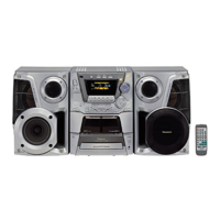
| Manufacturer | Panasonic |
| Model | SA-AK320P |
| Speaker Type | 2-way |
| CD Player | Yes |
| Radio Tuner | Yes |
| Bluetooth | No |
| USB Port | No |
| Number of Channels | 2 |
| Media Type | CD |
| Speaker Configuration | 2.0 |
| Input Sensitivity | 500mV |
| Signal-to-Noise Ratio | 70dB |
| Tuner Bands | FM, AM |
| Playback Formats | CD, MP3 |