EasyManua.ls Logo

Panasonic SA-AK785LM-K User Manual

Panasonic SA-AK785LM-K
143 pages
To Next Page IconTo Next Page
Page #1 background imageLoading...
Page #1 background image
© Panasonic Corporation 2009. All rights reserved.
Una
u
thorized copying and distribution is a violation
of law.
MEX0911001CE
CD Stereo System
Mode
Rev. 01
l No. SA-AK785LM-K
Product Color: (K)...Black Type
Notes: This model’s CD Mechanism Unit (CR14C). Please refer to the Original Service Manual
(Order No. MD0805031CE) for this CD Mechanism Unit.
Nota: El idioma original de este Manual de Servicio es en idioma inglés, sin embargo algunas notas aquí mencionadas serán escritas en español
para mejor descripción para Centros de Servicio de México.
SH-FX785
SB-AK785 SB-AK785SB-AK780 SB-AK780SA-AK785

Table of Contents

Question and Answer IconNeed help?

Do you have a question about the Panasonic SA-AK785LM-K and is the answer not in the manual?

Panasonic SA-AK785LM-K Specifications

General IconGeneral
USB PortYes
CD PlayerYes
Supported formatsMP3, WMA
FM RadioYes
FM TunerYes
BluetoothYes
Remote ControlYes
Speakers2
ConnectivityUSB, Bluetooth, AUX
Playable MediaCD-R, CD-RW

Summary

Safety Precautions

General Guidelines

Observes lead dress, protective devices, and leakage current checks.

Before Repair and Adjustment

Disconnect AC power and discharge capacitors before adjustments.

Safety Parts Information

Identifies critical safety parts and replacement guidelines.

Warning

Electrostatic Discharge (ESD) Prevention

Techniques to prevent damage to ES devices from static electricity.

Laser Diode Precautions

Precautions for handling laser diodes to prevent hazardous radiation exposure.

Traverse Unit Handling Precautions

Cautions for handling the traverse unit and optical pickup unit.

Specifications

Location of Controls and Components

Self-Diagnosis and Special Mode Setting

Doctor Mode Summary Table

Summary table for entering and using Doctor Mode functions.

Doctor Mode Tables

Details of Doctor Mode checks and operations (Tables 1, 2, 3, 4).

Service Mode Summary Table

Summary of Service Mode functions and their notes.

Service Mode Tables

Details of Service Mode checks (Tables 1, 2).

Reliability Test Mode (CD Mechanism Unit CR14C)

Progress flow chart for aging tests of the CD mechanism unit.

Error Code Table

Information on unit problems detected via error codes.

Troubleshooting Guide

Jupiter USB Troubleshooting

Troubleshooting guide for Jupiter USB issues.

F61/F76 Error Troubleshooting

Troubleshooting procedures for F61/F76 errors.

Disassembly and Assembly Instructions

Audio Digital Amp IC Replacement

Procedures for replacing Audio Digital Amp ICs (IC5400, IC5000, IC5200).

Switching Regulator IC Replacement

Procedure for replacing the switching regulator IC (IC5701).

Service Position

Voltage & Waveform Chart

Block Diagram

Schematic Diagram

CD Servo Circuit Schematic

Schematic diagram of the CD servo circuit.

Main Circuit Schematics

Schematic diagrams of the main circuit (9 parts).

Panel Circuit Schematics

Schematic diagrams of the panel circuit (2 parts).

Memory / MPort/Headphone / Mic Circuit Schematic

Schematic diagram for memory, MPort, mic circuits.

D-Amp Circuit Schematics

Schematic diagrams of the D-Amp circuit (2 parts).

Jupiter Circuit Schematics

Schematic diagrams of the Jupiter circuit (4 parts).

SMPS Circuit Schematics

Schematic diagrams of the SMPS circuit (2 parts).

Printed Circuit Board Layouts

Terminal Function of ICs

Exploded View and Replacement Parts List

Exploded View and Mechanical Parts List

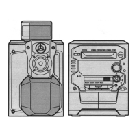
Exploded view showing mechanical part locations and their list.

Electrical Replacement Parts List

List of electrical components (ICs, resistors, capacitors, etc.) for replacement.

Related product manuals