EasyManua.ls Logo

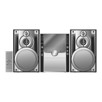
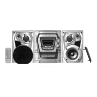
Panasonic SA-AK48 Service Manual

Panasonic SA-AK48
104 pages
To Next Page IconTo Next Page
Page #1 background imageLoading...
Page #1 background image
AMPLIFIER SECTION
PMPO
3000W
RMS power output
THD 10%, both channels driven
(HIGH) 40W per channel (6)
(MID) 40W per channel (6)
(LOW) 120W per channel (6)
(TOTAL) 200W per channel (6)
Input sensitivity
AUX
250mA
MIC
0.7mV
Input inpedance
AUX
13.9k
MIC
680
FM TUNER SECTION
Frequency range
87.50 - 108.00MHz
(50kHz steps)
Sensitivity
2.5µV (IHF)
S/N 26dB
2.2µV
Antenna terminal (s)
75 (unbalanced)
AM TUNER SECTION
Frequency range
552-1629kHz (9kHz steps)
Sensitivity
520-1630kHz (10kHz steps)
S/N 20dB (at 999kHz)
560µV/m
© 2000 Matsushita Electric Industrial Co., Ltd. All
rights reserved. Unauthorized copying and
distribution is a violation of law.
SA-AK48
Colour
(S) ................. Silver Type
Areas
(GC) .............. Asia, Latin America,
Middle East and Africa.
TAPE SECTION : AR2 MECHANISM SERIES
CD SECTION : RAE0152Z-M TRAVERSE DECK
SERIES
SYSTEM : SC-AK48
CASSETTE DECK SECTION
Track system
4 track, 2 channel
Heads
Record/playback
Soild permalloy head
Erasure
Double gap ferrite head
Motor
DC servo motor
Recording system
AC bias 100kHz
Erasing system
AC erase 100kHz
Tape speed
4.8cm/s
Frequency response (+3, -6dB) at DECK OUT
NORMAL (TYPE I)
35Hz - 14kHz
HIGH (TYPE II)
35Hz - 14kHz
S/N
50dB (A weighted)
Wow and flutter
0.18% (WRMS)
Fast forward and rewind time
Approx. 120 seconds with
C-60 cassette tape
CD SECTION
Sampling frequency
44.1kHz
Decoding
16 bit linear
Beam source/wave length
Semiconductor laser/
780nm
Number of channels
Stereo
Frequency response
20Hz - 20kHz (+1dB, -2dB)
Wow and flutter
Below measurable limit
Digital filter
8fs
CD Stereo System
Specifications
ORDER No.MD0004060C3

Table of Contents

Question and Answer IconNeed help?

Do you have a question about the Panasonic SA-AK48 and is the answer not in the manual?

Panasonic SA-AK48 Specifications

General IconGeneral
Power Output120 W
Speakers2
CD PlayerYes
RadioYes
Tuner BandsFM/AM
BluetoothNo
USB PlaybackYes
OutputsHeadphone
Weight (main unit)3.5 kg
Number of Channels2
InputsAUX
Playback FormatsCD, MP3

Summary

Product Specifications

Cassette Deck Section

Details track system, heads, motor, tape speed, frequency response.

CD Section

Specifies sampling frequency, decoding, and frequency response.

Handling Precautions for Traverse Deck

Electrostatic Discharge Prevention

Details grounding for static electricity prevention during servicing.

Traverse Deck Replacement Caution

Warns about laser diode protection and solder removal.

Laser Diode Precautions

Laser Safety Warnings

Advises against disassembling the pickup unit and adjusting the laser.

Operation Checks and Component Replacement

Checking the Main P.C.B.

Describes procedures for checking the main printed circuit board.

Disassembly Procedures

Covers disassembly for the CD changer, disc tray, and mechanism.

Replacement for the Traverse Deck Assy

Provides steps for replacing the traverse deck assembly.

Replacement for the Disc Tray

Details the procedure for replacing the CD disc tray.

Disassembly and Reassembly for Mechanism Base Drive Unit

Instructions for disassembling and reassembling the mechanism base drive unit.

Replacement for the Pinch Roller Assy and Head Block

Procedure for replacing the pinch roller and head block assembly.

Self-Diagnostic Functions

Error Code Descriptions

Cassette Mechanism Error Detection

Lists error codes and problems related to the cassette mechanism.

CD/Changer Block Error Detection

Details error codes for CD and changer block issues.

Measurement and Adjustments

Cassette Deck Section Adjustments

Details instruments and procedures for tape speed and azimuth adjustments.

Schematic Diagram Reference

Schematic Diagram Details

Provides detailed circuit diagrams for the unit's sections.

Printed Circuit Board Layouts

System Block Diagram

Troubleshooting Guide

CD Playback Troubleshooting Flowchart

A step-by-step guide for diagnosing CD playback issues.

Wiring Connection Diagram

Overall Unit Wiring Connections

Shows how different PCBs and components are interconnected.

IC Terminal Functions

Servo System ICs (IC701, IC702, IC703)

Explains the pins and functions of Servo Amp, Processor, and Motor Drive ICs.

Replacement Parts List

Mechanism Parts Location Diagrams

CD Mechanism Parts Location Diagrams

Related product manuals