Do you have a question about the Panasonic SA-AKX14LM-K and is the answer not in the manual?
General instructions for safe servicing of electronic equipment.
Procedure for checking leakage current when the unit is unplugged.
Procedure for checking leakage current while the unit is powered on.
Precautions before performing repairs or adjustments.
Explains the function and troubleshooting of the unit's protection circuit.
Important warnings and procedures for replacing fuses.
Lists critical safety components and the need for specified replacements.
Techniques to prevent damage to sensitive electronic components.
Safety measures when working with the laser diode.
Guidelines for using lead-free solder in service repairs.
Special care for traverse unit and optical pickup.
Worktable and human body grounding for ESD prevention.
Overview of manual content and ordering.
Details on supported media formats for CDs and USB.
Explains the function of each button on the remote control.
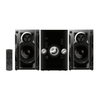
Identifies and explains the buttons on the main unit.
Steps for connecting speakers and the AC power cord.
Procedure to initialize the unit to shipping mode or perform a cold start.
Table detailing various diagnostic modes and their operations.
Specific diagnostic modes like Doctor Mode, EEPROM check, and Cold Start.
Details diagnostic modes for volume check, FL display, and CD mechanism reliability tests.
Diagnostic modes for CD self-adjustment results and LSI version check.
Process flow charts for aging tests of the CD mechanism unit.
Explains how to enter and use the self-diagnostic mode for troubleshooting.
Lists error codes and their corresponding diagnostic contents for the unit.
Specific error codes related to the power supply unit.
Error codes specific to the CD mechanism unit.
Procedures to enter and cancel the sales demonstration lock mode.
Steps to activate the sales demonstration lock function.
Steps to deactivate the sales demonstration lock function.
Identifies component locations on PCBs for troubleshooting.
Procedures for diagnosing specific error codes (F61/F76).
Identifies components on the SMPS circuit board.
Identifies components on the main circuit board.
Details operation and control of the D-Amp IC.
Visual guide showing disassembly sequence.
Illustrates placement of components and PCBs.
Step-by-step instructions to remove the top casing.
Instructions for removing the panel circuit board.
Steps to remove the main circuit board.
Procedure for replacing a voltage regulator transistor.
Steps for replacing the audio digital amplifier IC.
Procedure for replacing the switching regulator IC.
Instructions for removing the CD mechanism unit.
Steps to remove the rear panel of the unit.
Steps to remove the traverse unit from the CD mechanism.
Steps to install the traverse unit into the mecha chassis.
Steps to remove the CD servo circuit board.
Procedures for checking and repairing the main circuit board.
Procedures for checking and repairing the panel circuit board.
Procedures for checking and repairing the LCD circuit board.
Procedures for checking and repairing the SMPS circuit board.
Procedures for checking and repairing the CD servo circuit board.
High-level overview of the unit's functional blocks and connections.
Detailed diagram of the unit's power supply and distribution system.
Block diagram of the servo and system control circuitry.
Block diagram illustrating the audio signal path and processing.
Block diagram of the power supply circuitry.
Explains symbols, notations, and component identification used in schematics.
Detailed schematic of the CD servo control circuit.
Detailed schematic of the main circuit board.
Schematic for panel, LCD, remote sensor, and USB circuits.
Schematic of the tuner circuit.
Schematic of the SMPS (power supply) circuit.
Component layout diagram for the CD servo circuit board.
Component layout diagrams for main and tuner circuit boards.
Component layout diagrams for panel, LCD, remote, and USB boards.
Component layout diagram for the SMPS circuit board.
Table of expected voltage and waveform values for CD servo circuit.
Voltage and waveform data for CD Servo PCB pins.
Voltage and waveform data for Main PCB pins.
Voltage and waveform data for Main PCB pins.
Voltage and waveform data for LCD PCB pins.
Voltage and waveform data for Tuner PCB pins.
Voltage and waveform data for SMPS PCB pins.
Visual examples of waveforms for key ICs during operation.
Visual illustrations of various ICs, transistors, and diodes used in the unit.
Lists pin terminal functions for various ICs.
Pin terminal functions for the microprocessor IC.
Pin terminal functions for the FL driver IC.
List of mechanical parts with part numbers and quantities.
Diagram showing the location of cabinet parts for replacement.
Diagrams illustrating the unit's packaging process and materials.
List of mechanical parts with part numbers and quantities.
List of electrical components with part numbers and descriptions.
| Speaker Type | 2-way |
|---|---|
| Bluetooth | Yes |
| USB Playback | Yes |
| FM Radio | Yes |
| Number of Discs | 1 |
| Playable File Types | MP3, WMA |
| CD Player | Yes |
| Type | Stereo System |