Do you have a question about the Panasonic SA-AKX36LMK and is the answer not in the manual?
| Brand | Panasonic |
|---|---|
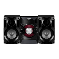
| Model | SA-AKX36LMK |
| Category | Stereo System |
| Language | English |
Essential safety rules for servicing the equipment.
Cautions and procedures before starting repair or adjustment.
Explains the function and reset procedure for protection circuitry.
Details the SMPS module used for powering the unit.
Lists critical safety parts requiring specific replacement.
Techniques to prevent damage to sensitive electronic components from ESD.
Safety precautions when working with the product's laser diode.
Guidance on using lead-free solder and related precautions.
Cautions for handling the optical pickup unit and traverse unit.
Methods for grounding to prevent electrostatic discharge damage.
General information for service personnel and order placement.
Step-by-step guide for updating the unit's firmware.
Details of amplifier output power and frequency response.
Specifications related to USB connectivity and file formats.
Specifications for FM/AM tuner, sensitivity, and input terminals.
Information on CD playback, laser wavelength, and channels.
Details on internal memory capacity and recording format.
Specifications for speakers, impedance, and sound pressure.
General specifications like power supply, dimensions, and operating conditions.
Details about compatible media formats and disc playback.
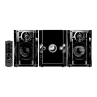
Explains the function of each button on the remote control.
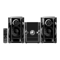
Describes the operation of buttons on the main unit.
Guides on connecting speakers, antennas, and the AC power cord.
Procedure to initialize the unit to shipping mode.
Details on entering Doctor Mode and EEPROM checksum check.
Explains volume setting, FL display, traverse, and reliability tests.
Details CD self-adjustment and LSI version checks.
Explains error codes and their diagnosis for power supply issues.
Procedure to activate the sales demonstration lock mode.
Procedure to deactivate the sales demonstration lock mode.
Identifies different types of screws used in the unit.
Step-by-step guide to remove the digital amplifier IC.
Step-by-step guide to install and solder the digital amplifier IC.
Procedure for checking panel, LED, and microphone PCBs.
Steps for checking the main PCB on its B side.
Block diagram illustrating servo and system control functions.
Explains symbols, notes, and safety precautions for diagrams.
Layout diagram for the main printed circuit board (Side A).
Table of voltage values for various ICs and modes.
Voltage values for the Panel PCB across different ICs.
Visual exploded view of cabinet parts with their locations.