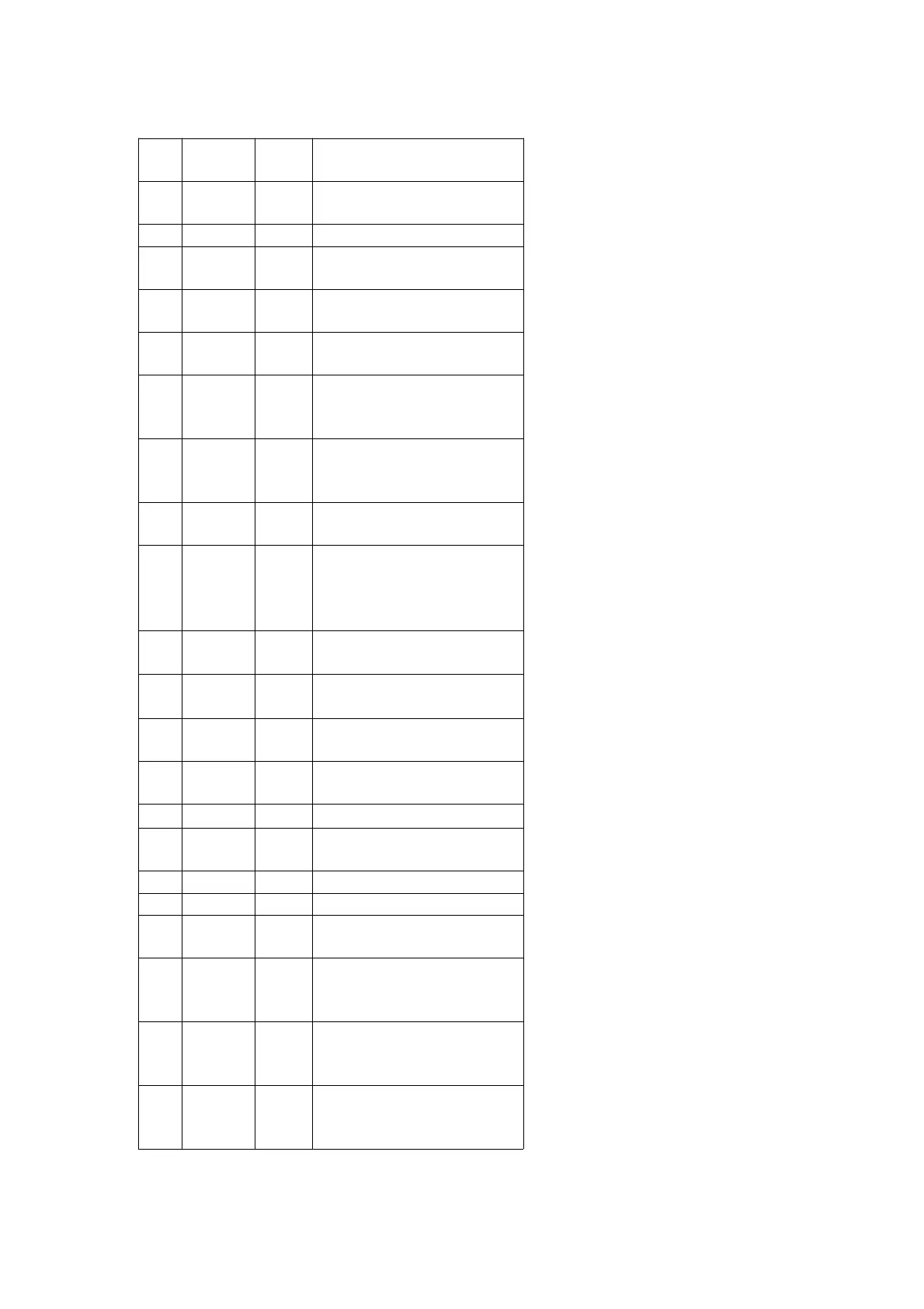
Pin
No.
Mark I/O Function
19
PROTECT
I Erase prevention switch
signal input terminal
20 MMOD — Connected to GND
21 RST I Reset signal input terminal
(“L”:Reset)
22 UNIT
TEST
I Test signal input terminal
(Open)
23 CS2 I Test signal input terminal
(Open)
24 SCTSY I Micro computer interrupt
signal input terminal (SUBQ
/ADIP simultaneous signal)
25 MDISY I Micro computer interrupt
signal input terminal (MD
simultaneous signal)
26 PANEL
REQ
I Panel I/F request signal
input terminal
27
~ 29
LED
OUT1
~ LED
OUT3
O Drive signal output
terminal to LED DRIVE (“H”
:LED ON)
30 TEST02 O Test signal output terminal
(Not used, open)
31
V
DD
2(3V)
I Power supply terminal (+
3V)
32 OSC1 I Crystal oscillator input
terminal (f=10.02MHz)
33 OSC2 O Crystal oscillator output
terminal (f=10.02MHz)
34
V
SS
— GND terminal
35 X1 I Not used, connected to
GND
36 X0 O Not used, open
37 VSS — GND terminal
38 TEST03 O Test signal output terminal
(Not used, open)
39 EEPCS O EEPROM chip select signal
output terminal (Not used,
open)
40 EEPCK O EEPROM clock signal
output terminal (Not used,
open)
41
EEPDATA
I/O EEPROM data in/output
terminal (Connected to
GND through resistor)
45