Do you have a question about the Panasonic SA-PM10 and is the answer not in the manual?
Details amplifier output power, impedance, and headphone specifications.
Outlines tape system, heads, recording, erasing, speed, and frequency response.
Provides details on sampling frequency, decoding, laser wavelength, and D/A conversion.
Explains causes and procedures for protection circuit activation during operation.
Offers important safety instructions for replacing the AC mains lead.
Provides essential safety warnings and precautions related to the laser diode.
Outlines procedures for checking unit operation and replacing major components.
Describes how to check the functionality of main printed circuit boards.
Details the process for replacing key components within the unit.
Guides on replacing pinch rollers and head blocks in the cassette mechanism.
Outlines the replacement process for motors and various belts in the cassette mechanism.
Explains how to use the unit's self-diagnostic feature to identify malfunctions.
Covers essential measurements and adjustments for optimal performance.
Provides detailed electrical circuit diagrams for troubleshooting and repair.
Details terminal functions of the SERVO PROCESSOR.
Details terminal functions for motor drive ICs.
Provides detailed lists and locations of all replaceable parts for the unit.
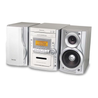
| Brand | Panasonic |
|---|---|
| Model | SA-PM10 |
| Category | Stereo System |
| Language | English |