EasyManua.ls Logo

Panasonic SA-PM28E User Manual

Panasonic SA-PM28E
169 pages
To Next Page IconTo Next Page
Page #1 background imageLoading...
Page #1 background image
Order No. MD0304130C2
CD Stereo System
SA-PM28E / SA-PM28EB / SA-PM28EG
Color
(S) ... Silver Type
SPECIFICATIONS
Specification
1
Question and Answer IconNeed help?

Do you have a question about the Panasonic SA-PM28E and is the answer not in the manual?

Panasonic SA-PM28E Specifications

General IconGeneral
TypeMini Hi-Fi System
Speaker Configuration2.0
CD PlayerYes
Number of Discs1
Radio TunerFM/AM
BluetoothNo
USB PortNo
Remote ControlYes
Speakers2
Playable MediaCD-R, CD-RW
Power SupplyAC 220-240 V, 50 Hz

Summary

SPECIFICATIONS

Specification

Summary of product specifications including electrical and mechanical details.

Amplifier Section

FM Tuner Section

AM Tuner Section

Cassette Deck Section

CD Section

General

Power Supply

Details of voltage and frequency for power supply requirements.

Dimensions

Physical dimensions of the unit (W x H x D).

Mass

Weight of the unit.

System

System: SC-PM28 (E)

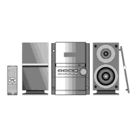
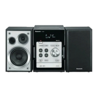
System configuration details for model E.

System: SC-PM28 (EB)

System configuration details for model EB.

System: SC-PM28 (EG)

System configuration details for model EG.

1. Before Repair and Adjustment

2. Protection Circuitry

3. Accessories

4. Caution for AC Main Lead

5. Front Panel Controls

Front Panel Controls (Main Unit)

6. Handling the Lead-free Solder

6.1. About lead free solder (PbF)

Information about lead-free solder and handling precautions.

7. Handling Precautions For Traverse Deck

Handling Precautions For Traverse Deck (Continued)

Grounding for electrostatic breakdown prevention

Methods for grounding to prevent electrostatic breakdown.

8. Disassembly and Main Component Replacement Procedures

PCB Checking Procedures

Procedures for checking various Printed Circuit Boards (PCBs).

Cassette Mechanism Replacement

Steps to replace components within the cassette mechanism.

CD Mechanism Replacement

Steps to replace components within the CD mechanism.

Traverse Mechanism Procedures

Procedures related to the traverse mechanism disassembly and handling.

CR16 Mechanism Procedures

Disassembly and assembly procedures for the CR16 mechanism.

8.1.6. Replacement of the Power Amplifier IC

8.2. Procedure for Replacing Cassette Holder

8.3. Procedure for Replacing Pinch Roller and Head Block (Cassette Mechanism Unit)

8.4. Procedure for Replacing Motor, Capstan Belt A, Capstan Belt B, and Winding Belt (Cassette Mechanism Unit)

8.5. Procedure for Replacing Parts on Mechanism PCB

8.6. Replacement for CD traverse deck

8.7. Replacement for optical pickup unit (CD mechanism)

8.8. Replacement for a traverse gear A and a traverse gear B

8.9. Procedure for removing CD loading mechanism

8.10. CR16 mechanism disassembly procedure

8.10.2. Replacement for the disc tray

Steps to replace the disc tray.

8.10.3. Replacement for the traverse deck

Steps to replace the traverse deck assembly.

8.10.4. Disassembly for CD loading unit

Steps for disassembling the CD loading unit.

8.11. CR16 MECHANISM ASSEMBLY PROCEDURE

Grease and Oil Application

Application of specific grease and oil for mechanism assembly.

8.12. Disassembly for traverse mechanism

8.13. Handling of cassette tape jam

9. Self-Diagnostic Display Function

9.1. Preparations

Preparations for using the self-diagnostic function.

9.2. Setting of the Self-Diagnostic Mode

Steps to enter the self-diagnostic mode.

9.3. Restoring Normal Display

Procedures to restore normal display after self-diagnosis.

9.4. Clearing Self-Diagnostic Memory

Steps to clear the self-diagnostic memory.

9.5. Displaying Self-Diagnostic Results

10. Precaution of Laser Diode

11. Procedure for Checking Operation of Individual Parts of Cassette Mechanism Unit

11.1. Operation Check with Cassette Tape

Steps for checking cassette mechanism operation using a tape.

11.2. Operation Check without Cassette Tape

12. Measurement And Adjustments

Tuner Section Alignment

Procedures for aligning the tuner section, including AM-IF alignment.

Cassette Deck Section Adjustments

Requirements and settings for cassette deck section adjustments.

12.2.4. Tape Speed Adjustment

12.2.5. Bias Voltage Check

12.2.6. Bias Frequency Check

13. Block Diagram

14. Schematic Diagram

15. Printed Circuit Board

16. Wiring Connection Diagram

17. Troubleshooting Flowchart (CD Section Circuit)

18. Type Illustrations of ICs, Transistors & Diodes

19. Terminal Function of IC’s

19.1. IC701 (AN22004A-NF) Servo Amplifier

Pin description and function for IC701 Servo Amplifier.

19.4. IC302 (C2CBJF000007) System Microprocessor

Pin description and function for IC302 System Microprocessor.

20. Parts Location and Replacement Parts List

Deck Mechanism Parts

Location and list of parts for the deck mechanism assembly.

CD Loading Mechanism Parts

Location and list of parts for the CD loading mechanism.

Cabinet Parts

Location and list of parts for the cabinet assembly.

Electrical Components List

Comprehensive list of electrical parts including PCBs, ICs, transistors, diodes, resistors, etc.

20.5. Packing Materials & Accessories Parts List

PACKING MATERIALS

List of packing materials used for the product.

ACCESSORIES

List of included accessories like remote control, cords, and antennas.

Schematic Diagrams

A CD SERVO CIRCUIT

Schematic for the CD servo circuit.

B MAIN P.C.B

Schematic for the main PCB.

G DECK P.C.B

Schematic for the deck PCB.

H DECK MECHANISM P.C.B

Schematic for the deck mechanism PCB.

C PANEL P.C.B

Schematic for the panel PCB.

J POWER P.C.B

Schematic for the power PCB.

A CD SERVO P.C.B

Schematic for the CD servo PCB.

L TACT SWITCH P.C.B

Schematic for the tact switch PCB.

E AC LED P.C.B

Schematic for the AC LED PCB.

F HEADPHONE P.C.B

Schematic for the headphone PCB.

D SENSOR P.C.B

Schematic for the sensor PCB.

I TAPE EJECT P.C.B

Schematic for the tape eject PCB.

K AC TRANSFORMER P.C.B

Schematic for the AC transformer PCB.

Schematic Diagram - 2

Schematic diagram for the unit.

B MAIN (TUNER) CIRCUIT

Schematic for the main tuner circuit.

Schematic Diagram - 5

Schematic diagram for the unit.

Schematic Diagram - 6

Schematic diagram for the unit.

Schematic Diagram - 7

Schematic diagram for the unit.

Schematic Diagram - 8

Schematic diagram for the unit.

Schematic Diagram - 9

Schematic diagram for the unit.

Schematic Diagram - 10

Schematic diagram for the unit.

Schematic Diagram - 11

Schematic diagram for the unit.

Schematic Diagram - 12

Schematic diagram for the unit.

Schematic Diagram - 13

Schematic diagram for the unit.

Schematic Diagram - 14

Schematic diagram for the unit.

Schematic Diagram - 15

Schematic diagram for the unit.

Schematic Diagram - 16

Schematic diagram for the unit.

Wiring Diagram

Schematic Diagram - 1 (Continued)

A CD SERVO CIRCUIT

Schematic for the CD servo circuit.

Schematic Diagram - 2 (Continued)

Schematic Diagram - 3 (Continued)

B MAIN (TUNER) CIRCUIT

Schematic for the main tuner circuit.

Related product manuals