Do you have a question about the Panasonic SA-PM45PC and is the answer not in the manual?
Details on amplifier output power, impedance, and terminals.
Frequency range and sensitivity for FM and AM tuners.
Information on supported disc types, sampling frequency, bit rate, and decoding.
Details on playable USB media and supported audio file formats.
Observing lead dress, protective devices, and leakage current checks.
Discharging capacitors, avoiding shorts, and gradual power restoration.
Understanding protection circuitry and proper fuse replacement procedures.
Identifying critical safety components and replacement part requirements.
Techniques to prevent damage to sensitive devices from static discharge.
Guidelines for handling and avoiding exposure to laser radiation.
Precautions for static breakdown prevention when handling the traverse deck.
General description and service cautions for using lead-free solder (PbF).
List of accessories included with the product, such as remote control and antennas.
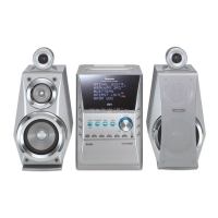
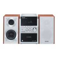
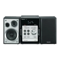
Description of buttons and functions on the main unit.
Explanation of functions for each button on the remote control.
Details on playing MP3 files, CD-DA, and DualDiscs.
Overview of service modes, including Doctor Mode and specific test modes.
Procedures for CD self-adjustment results and explanation of error codes.
Important cautions, screw types, and disassembly flow chart.
Step-by-step guide for removing side panels, top cabinet, and front panel.
Procedures for removing USB PCB, panel PCBs, and internal components.
Detailed steps for disassembling the CD mechanism, traverse unit, and gears.
Procedures for checking and repairing specific PCBs.
Steps for accessing and repairing the transformer PCB.
Guidance for checking and repairing the main circuit board.
Procedures for checking and repairing the CD servo PCB.
Steps for checking and repairing the USB PCB.
Standard voltage values for CD Servo, Main, Panel, Transformer, and USB PCBs.
Reference waveforms for various test points during operation.
Diagram illustrating the interconnection of all PCBs and components.
Functional block diagram for the CD servo and optical pickup.
Block diagram for the main unit and USB module.
Block diagram connecting main, panel, and transformer circuits.
Key to symbols, switch functions, safety notices, and capacitor/resistor values.
Detailed schematic for the CD servo circuit.
Detailed schematic for the main processing and audio circuits.
Schematic for the front panel, headphone jack, and music port.
Schematic detailing the power transformer and associated circuitry.
Schematic for the USB interface and controller.
Component layout diagrams for CD servo and USB PCBs.
Component layout diagram for the main printed circuit board.
Component layout diagrams for panel, headphone, and music port PCBs.
Component layout diagram for the transformer PCB.
Visual representations and part numbers for key ICs, transistors, and diodes.
Detailed pin descriptions for the servo processor IC.
Pin descriptions for the 4CH drive IC and microprocessor.
Diagram showing the location of external cabinet parts.
Diagram detailing the parts within the CD mechanism.
Illustration and list of items included in the product packaging.
Comprehensive list of replaceable parts including part numbers and descriptions.
| Brand | Panasonic |
|---|---|
| Model | SA-PM45PC |
| Category | Stereo System |
| Language | English |