Do you have a question about the Panasonic SA-PM24EB and is the answer not in the manual?
General safety guidelines for servicing the equipment.
Safety precautions related to the AC power cord and plug.
Precautions before starting repair or adjustment procedures.
Lists safety-critical components and their part numbers.
Techniques to prevent damage from static electricity to sensitive components.
Precautions for handling the laser diode and avoiding hazardous radiation exposure.
Information about lead-free solder used in the equipment and its properties.
Specific precautions for handling the optical pickup unit to prevent damage.
Methods for grounding to prevent electrostatic damage to sensitive parts.
Contains technical information for servicing the model.
Technical specifications for the amplifier section.
Specifications for tuner and input/output terminals.
Specifications related to disc playback capabilities.
Specifications for the USB port and file support.
General specifications like power supply, dimensions, and operating conditions.
Description of the buttons and their functions on the main unit.
Description of the buttons and their functions on the remote control.
Information about compatible media formats and their usage.
Procedure to enter the unit's self-diagnostic mode.
Explanation of error codes displayed during self-diagnosis.
Procedure to enter Doctor Mode and details of test tables.
Guide to diagnose and resolve common unit problems based on symptoms.
Lists necessary tools and fixtures for service operations.
Chart showing the sequence for disassembling the unit's components.
Diagram showing the location of major internal parts.
Step-by-step guide to remove the top cabinet.
Step-by-step guide to remove the front panel assembly.
Step-by-step guide to remove the USB PCB.
Step-by-step guide to remove the panel PCB.
Step-by-step guide to remove the FL window.
Step-by-step guide to remove the centre ornament.
Step-by-step guide to remove the CD lid.
Step-by-step guide to remove the main PCB.
Step-by-step guide to remove the power PCB.
Procedure for replacing the power amplifier IC.
Step-by-step guide to remove the transformer PCB.
Procedure for replacing the transistor Q5901.
Step-by-step guide to remove the CD mechanism unit.
Step-by-step guide to remove the CD servo PCB.
Procedures for disassembling the traverse unit.
Procedures for assembling the traverse unit.
Guide for checking and repairing the USB PCB.
Guide for checking and repairing the Panel PCB.
Guide for checking and repairing the Transformer PCB.
Guide for checking and repairing the Main PCB.
Guide for checking and repairing the Power PCB.
Guide for checking and repairing the CD Servo PCB.
Voltage measurement data for the CD Servo PCB.
Voltage measurement data for the Main PCB (part 1).
Voltage measurement data for the Main PCB (part 2).
Voltage measurement data for the Power PCB.
Voltage measurement data for the Transformer PCB.
Chart showing various signal waveforms in the unit.
Visual representations of integrated circuits, transistors, and diodes.
Diagram illustrating the flow of control signals within the unit.
Diagram showing how different blocks of the unit are connected.
Block diagram of the servo and system control functions.
Block diagram illustrating the audio signal path.
Block diagram of the power supply system.
Diagram showing the electrical wiring connections between components.
Explanations of symbols and notations used in schematic diagrams.
Schematic diagram of the CD servo circuit.
Schematic diagram of the main circuit (part 1/4).
Schematic diagram of the main circuit (part 3/4).
Schematic diagram of the main circuit (part 4/4).
Schematic diagram of the panel circuit.
Schematic diagram of the USB circuit.
Schematic diagram of the transformer circuit.
Schematic diagrams for power and headphone circuits.
Printed circuit board layouts for CD Servo and Panel.
Printed circuit board layouts for Main and USB PCBs.
PCB layouts for Headphone, Power, and Transformer boards.
Terminal functions and pin descriptions for the main microprocessor IC800.
Exploded view and list of mechanical replacement parts.
Details about the product's packaging and included accessories.
Detailed list of mechanical replacement parts with part numbers.
Detailed list of electrical replacement parts with part numbers.
| Brand | Panasonic |
|---|---|
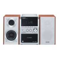
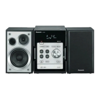
| Model | SA-PM24EB |
| Category | Stereo System |
| Language | English |