Do you have a question about the Panasonic SA-PM29E and is the answer not in the manual?
Details amplifier specifications including power output, distortion, and impedance.
Specifies FM tuner parameters such as frequency range and sensitivity.
Details AM tuner parameters like frequency range and sensitivity.
Outlines CD player specifications including disc compatibility and frequency response.
Lists cassette deck specifications such as track system and head type.
Outlines the general procedure for checking the unit during service.
Details how to check the main printed circuit boards.
Lists necessary items and preparations for self-diagnosis.
Explains how to enter the self-diagnostic mode.
Describes the procedure to return to normal display mode.
Details how to clear stored diagnostic memory.
Explains how to view self-diagnostic error codes and results.
Step-by-step guide for checking cassette mechanism operation with a tape.
Instructions for checking cassette mechanism operation without a tape.
Procedures for measuring and adjusting cassette deck parameters.
Steps to adjust the tape playback speed.
Procedure to check the bias voltage level in the cassette deck.
Procedure to check the bias frequency output.
Illustrates the functional blocks of the CD servo system.
Shows the overall block diagram of the main system components.
Detailed schematic of the CD servo control circuit.
Schematic diagram of the main processing and control circuits.
Schematics for user interface components like panel, switches, and headphone jack.
Schematics for the cassette deck mechanism and tape eject functions.
Schematic showing the power supply and regulation stages.
Schematics for power transformer connections and speaker outputs.
Schematic illustrating the CD tray loading mechanism circuit.
Layout diagrams for the CD servo printed circuit boards.
Layout diagram for the main printed circuit board.
Layout diagrams for panel and tact switch PCBs.
Layout diagrams for deck and tape eject printed circuit boards.
Layouts for deck mechanism and CD loading printed circuit boards.
Layout diagram for the power supply printed circuit board.
Layout diagram for the transformer printed circuit board.
Details terminal functions for IC701, the head amplifier.
Explains terminal functions for IC702, the LSI chip.
Lists terminal functions for IC703, the 4-channel drive IC.
Details terminal functions for IC302, the microprocessor.
Identifies and lists parts for the cassette deck mechanism.
Identifies and lists parts for the CD loading mechanism.
Lists all cabinet and chassis components.
Comprehensive list of all electrical components used in the unit.
Lists packaging materials and included accessories.
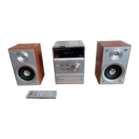
| CD Player | Yes |
|---|---|
| Bluetooth | No |
| USB Port | No |
| Speaker type | 2-way |
| Woofer diameter | 10 cm |
| Power Supply | AC 220-240V, 50/60Hz |
| Type | Micro System |
| Tuner | FM |
| RMS Output Power | 20W per channel |
| Impedance | 6 Ω |
| Tuner Bands | FM |
| Disc Types | CD, CD-R, CD-RW |
| Playback Formats | CD-DA |


 Loading...