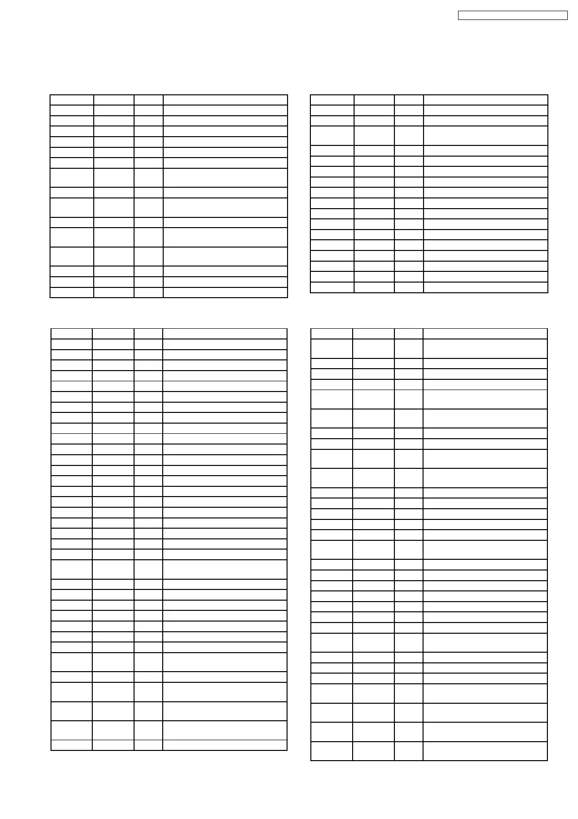
Pin No. Mark I/O Function
1 LPD I APC Amp input terminal
2 LD O APC Amp. output terminal
3 VCC I Power source terminal
4 EQSW - Equalizer switch terminal
5 RFOUT O RF summing Amp output terminal
6 RFIN I AGC input terminal
7 CAGC - AGC loop filter connecting
capacitor terminal
8 AGC O AGC output terminal
9 HPF-
AMP
- HPF Amp connecting capacitor
terminal
10 3TOUT O 3TOUT output terminal
11 HPFDET - Detection system’s HPF
connecting capacitor terminal
12 OFT
CONT
- PFTR detection level adjustment
terminal
13 BDO O BDO output terminal
14 OFTR O OFTR output terminal
15 /RFDET O NRFDET output terminal
Pin No. Mark I/O Function
1 DRVDD I DRAM interface power supply
2 D0 I/O DRAM data input-output 0
3 D1 I/O DRAM data input-output 1
4 NWE O DRAM ROM enable signal
5 NRAS O DRAM RAS control signal
6 D2 I/O DRAM data input-output 2
7 D3 I/O DRAM data input-output 3
8 NCAS0 O DRAM CAS control 0
9 NCASI O DRAM CAS control 1
10 A8 O DRAM Address 8
11 A7 O DRAM Address 7
12 A6 O DRAM Address 6
13 A5 O DRAM Address 5
14 A4 O DRAM Address 4
15 A9 O DRAM Address 9
16 A0 O DRAM Address 0
17 A1 O DRAM Address 1
18 A2 O DRAM Address 2
19 A3 O DRAM Address 3
20 DVSS2 - Digital GND
21 DVDD2 - Digital power supply
22 SPOUT O Spindle motor drive output signal
(absolute value output)
23 TRVP O Traverse drive output (+output)
24 TRVM O Traverse drive output (-output)
25 TRP O Tracking drive output (+output)
26 TRM O Tracking drive output (-output)
27 FOP O Focus drive output (+output)
28 FOM O Focus drive output (-output)
29 IOVDD1 - IO power supply
30 TBAL O Tracking balance adjustment
output
31 FBAL O Focus balance adjustment output
32 FE I Focus error signal input (analog
input)
33 TE I Tracking error signal input (analog
input)
34 RFENV I RF envelope signal input (analog
input)
35 OFT I Off track signal input (H: off track)
Pin No. Mark I/O Function
16 LDON - LDON terminal
17 GND - Earth terminal
18 EQBSY - Equalizer boost adjustment
terminal
19 VREF O VREF output terminal
20 TEN I Amp inverting input terminal
21 TEOUT O TE amp output terminal
22 FEN I Amp inverting input terminal
23 FEOUT O FE amp output terminal
24 GCTL - GCTL terminal
25 FBAL I FBAL control terminal
26 TBAL I TBAL control terminal
27 E O Tracking signal input terminal 1
28 F O Tracking signal input terminal 2
29 D O Tracking signal input terminal 4
30 B O Tracking signal input terminal 2
31 C O Tracking signal input terminal 3
32 A O Tracking signal input terminal 1
Pin No. Mark I/O Function
36 NRFDET I RF detective signal input (L:
detection)
37 BDO I Drop out signal input (H: drop out)
38 LDON O Laser ON signal input (H: ON)
39 ARF I RF signal input
40 IREF I/O Resistance terminal for current
electricity setting
41 ADP
VCC
I Analog power supply voltage
monitor input
42 DSLF I/O DSL loop filter terminal
43 RFSW I/O DSL loop filter terminal
44 PLLF I/O PLL loop filter terminal (phase
comparison)
45 PLLF0 I/O PLL loop filter terminal (speed
comparison)
46 AVDD2 I ”Analog power supply (DSL
47 AVSS2 - ”Analog ground (DSL
48 OUTL O L ch audio output
49 AVSS1 - Analog ground (audio output)
50 OUTR O R ch audio output
51 AVDD1 - Analog power supply (audio
output)
52 DVSS3 - Digital GND
53 DVDD3 - Digital power supply
54 IOVDD2 - IO power supply
55 FLAG O Flag output
56 EXT2 I/O Extension input-output port 2
57 EXT0 I/O Extension input-output port 0
58 EXT1 I/O Extension input-output port 1
59 REGON I ”In-housed regulator control (H:
ON
60 TX O Digital audio interface output
61 MCLK I Micon command clock input
62 MDATA I Micon command data input
63 MLD I Micon command load input (L:
Load)
64 BLKCK O Sub code block clock (f-75Hz:
normal play)
65 PWM
SEL
I ”PWM output mode switch input
(L: direct
66 SMCK O 4.2336MHz/8.4672MHz clock
output
22 Terminal Function of IC´s
22.1. IC701 (AN22004A-NF) IC HEAD AMP
22.2. IC702 (MN6627931BL) IC LSI
99
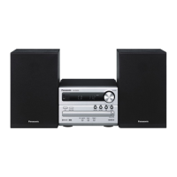
SA-PM29E / SA-PM29EB / SA-PM29EG


 To Next Page
 Loading...