Do you have a question about the Panasonic SA-PM250EB and is the answer not in the manual?
General guidelines for safe servicing procedures and precautions.
Procedure for checking leakage current with the unit unplugged.
Procedure for checking leakage current with the unit powered on.
Guidelines to prevent damage to sensitive electronic components from static discharge.
Safety precautions for handling the laser diode in the CD pickup unit.
General information for service personnel regarding technical details and ordering.
Describes the functions of controls on the main unit and remote.
Table detailing self-diagnostic modes, displays, and key operations.
Lists required service fixtures and tools for disassembly and assembly.
Visual guide illustrating the sequence of disassembly for internal components.
Identifies different types of screws used in the unit with their part numbers.
Diagram showing the location of major internal components and PCBs.
Step-by-step instructions for removing the top cabinet assembly.
Procedure for removing the Bluetooth Printed Circuit Board.
Procedure for removing the Tuner Printed Circuit Board.
Instructions for removing the Switching Mode Power Supply unit.
Procedure for removing the SMPS Printed Circuit Board.
Step-by-step instructions for removing the front panel assembly.
Procedures for removing button, volume, and panel PCBs.
Instructions for removing the CD lid assembly.
Step-by-step procedure for removing the Main Printed Circuit Board.
Instructions for removing the CD mechanism unit.
Procedure for removing the CD Interface Printed Circuit Board.
Step-by-step guide for disassembling the CD traverse unit.
Step-by-step guide for assembling the CD traverse unit.
Procedures for checking the SMPS PCB, including connections and diagnostics.
Procedures for checking the Panel PCB, including connections and diagnostics.
Procedures for checking the CD Interface PCB, including connections and diagnostics.
Procedures for checking the Main PCB, Side A, including connections and diagnostics.
Procedures for checking the Main PCB, Side B, including connections and diagnostics.
Block diagram illustrating the system control and audio signal flow.
Block diagram showing the power supply circuit and voltage distribution.
Explains symbols, notations, and safety notices used in schematic diagrams.
Schematic of CD Interface and Main (MICON) circuits, part 1 of 2.
Schematic of Main (MICON) circuit, part 2 of 2.
Schematic diagram of the main power supply circuit.
Schematic diagram of the main audio amplifier (DAMP) circuit.
Schematic diagram for the CD motor driver circuit within the main unit.
Schematic diagrams for the USB and Tuner circuits.
Schematic diagrams for Panel, Volume, and Button circuits.
Schematic diagram of the Switching Mode Power Supply (SMPS) circuit.
Layout diagram for the CD Interface and Tuner PCBs.
Layout diagram for the Main PCB, showing component placement on Side A.
Layout diagram for the Main PCB, showing component placement on Side B.
Layout diagrams for the Panel, Volume, and Button PCBs.
Layout diagram for the SMPS PCB, showing component placement.
Standard voltage values for various ICs and points on the Main PCB.
Visual representation of expected waveforms at specific test points.
Exploded view showing the location of cabinet parts and their reference numbers.
Diagram illustrating the packaging of the unit and its accessories.
List of mechanical parts, including their part numbers and descriptions.
List of electrical components, including ICs, transistors, diodes, etc., with part numbers.
| Brand | Panasonic |
|---|---|
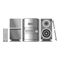
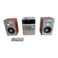
| Model | SA-PM250EB |
| Category | Stereo System |
| Language | English |